Introduction
Theory of Operation
The Dividers stage takes in the local oscillator's signal and divides it by 4, producing
two output signals. Each output signal is at a frequency that is ¼ the stage's
input signal and is a square wave with 50% duty cycle. The 50% duty cycle
is with respect to the4 5V rail.
The signals are "in quadrature", that is, they are 90° out of phase with each
other. These are provided to the TX and RX mixer stages as clocking signals. They
are called out on testpoints marked S0 and S1.
Schematic
This is a subset of the
overall schematic.
Note: red dot indicates resistor testpoints (hairpin, top, or left-hand lead)
Bill of Materials
| Designation | Value | Color/Code | Orientation | Category | Notes |
|---|
| U6 | 74AC74 | | 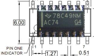 | SMT | |
| C21 | 0.01uF | | | SMT 1206 | |
| R09 | 10k |  | flat-h | | |
| R10 | 10k | | flat-v | | |
| C20 | 4.7uF | 475 | | ceramic | |
Summary Build Notes
- Install C21 (bottom)
- Install SMT U6 (bottom)
- Install 2 resistors (top)
- Install 1 ceramic capacitor (top)
- Test the Stage
Detailed Build Notes
Bottom of the Board
Install U6
| Designation | Value | Color/Code | Orientation | Category | Notes |
|---|
| U6 | 74AC74 | |
|
SMT SOIC-14 | |
Install C21 SNT Cap
| Designation | Value | Color/Code | Orientation | Category | Notes |
|---|
| C21 | 0.01uF | | | SMT 1206 | |
Top of the Board
Install Resistors
| Designation | Value | Color/Code | Orientation | Category | Notes |
|---|
| R09 | 10k | | flat-h | | |
| R10 | 10k | | flat-v | | |
Install Ceramic Capacitor
| Designation | Value | Color/Code | Orientation | Category | Notes |
|---|
| C20 | 4.7uF | 475 | | ceramic | |
Completed Stage
Topside
Bottomside
Testing
Current Draw(DMM)
- Current numbers here are for the CMOS version of the Si570. You will need
to adjust these up by about 14 mA for the LVDS version.
- Power the board up
- Measure the current draw and 5 V rail voltage with a 1K Ω limiting resistor
- Measure the current draw without the limiting resistor.
| Testpoint | Nominal Value | Author's | Yours |
|---|
| Current Limited mA | 6-10 mA | 7.5 mA | ______ |
| Current limited 5V rail | 1-2 Vdc | 975 mV | ______ |
| Non limited draw mA | 80-90 mA | 85.7 mA | ______ |
Voltage Tests (DMM)
If the output of the dividers are not as expected, check the voltages at the pins
of U6. Unexpected values here usually point to problems with soldering U5 and/or
the voltage dividing resistors R9 and R10. Using a DMM:
- Measure the output of the voltage divider with respect to ground. Measure at the
top lead of R10 (or the left-hand lead of R9). This should yield approximately ½ the
5 volt rail voltage.
- Measure the voltages (with respect to ground) on the pins of U6. It is best
to test for these voltages at the actual pins (not the pads), thereby ensuring correct
soldering of the pins to the pads.
| Testpoint | Nominal Value | Author's | Yours |
|---|
| Topside, R10's top lead | 2.5 Vdc | 2.50 Vdc | ______ |
| U6, Pins 1, 4, 10, 13, 14 | 5 Vdc | 4.96 Vdc | ______ |
| U6, pins 2, 3, 5, 6, 8, 9, 11, 12 | 2.5 Vdc | 2.48-3.50 Vdc | ______ |
| U6, pin 7 | 0 Vdc | 0 Vdc | ______ |
Test Center Frequency Output
- Connect a short piece of wire as an "antenna" for your HF RX and lay it over the
board
- No need to use the USB control in this test
- Apply power to the board
- Tune your radio to find the signal at 14.084 MHz (¼ the Si570 default frequency of 56.336 MHz
- If you can detect the signal and have passed the voltage tests above, your divider
stage is pretty well assured to be working correctly.
U5 Output (Optional Test)
In the event that you have or have access to a dual channel oscilloscope,
you can test the divider outputs here.
Do not attempt this measurement unless you have a calibrated scope of very good
quality and correctly compensated probes.
U5 sends I and Q signals to the mixer's S0 and S1 inputs.
- Use a dual channel oscilloscope, triggering on Channel 1
- Power up the board and plug in the USB cable
- Run Rocky and set the center frequency to 7.046 MHz
- measure the S0 and S1 outputs at the corresponding testpoints on the top side of
the board, as indicated above.
- They should both be the same frequency (¼ of the LO Output - assuming you
use the settings from the LO test, that would be 7.046 mHz) and should be
in quadrature (90° out of phase with each other). The image below shows
approximations of p-p voltages and frequencies of the 2 quadrature signals.
- They should be approximately 5 volt p-p square waves. The square waves may have
a fair amount of ringing on them depending a bit on your scope quality and connection to the
circuit board (see Waveforms below).
Divider Output Waveforms (Quadrature, 7.046 MHz)