Introduction
Summary Build Notes
- Set up Rocky's ".INI" file for Multiband OperationConnect the I and Q output lines
- Connect the Antenna
- Connect the power leads/connector
- Test the Stage
Detailed Build Notes
Setting up Rocky.ini File for Multiband Operation
If you are using Rocky, you should set up the ".INI" file in Rocky (rocky.ini) to allow for multi-band operation. This process is simple and involves adding lines in the "[Bands]" section of rocky.ini to designate the text to display for and the center frequency ofeach band selection.
For details, see the example in this link.
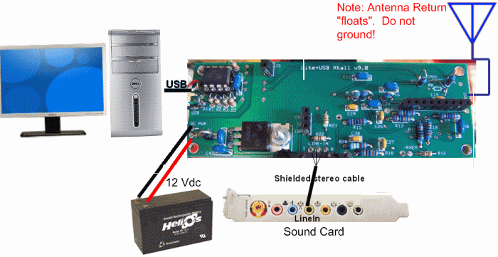
RX I and Q Audio output - LINE IN
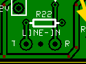
These are the Ring(Q) and Tip audio outputs of the board, located at the bottom center edge of the board.
Depending upon your ultimate
enclosure/mounting requirements, you want to connect these three pads to good quality shielded
2 conductor audio cable, terminated either by a 3.5 mm mini plug or a mini jack.
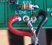
Use a short length of solid hookup wire, soldered to the shielding and to the ground/common connection, and wrapped firmly around
the outer insulation of the cable as a strain relief mechanism.
Antenna Connection

Sample Antenna Connection
ANT/RET
These are the ANT and (unmarked) Return connections located on the right-hand side of the board, near the top.
Use RG-174U 50 ohm "micro" coax for the antenna connection, There is a good discussion of RG-174 coax and techniques for installing connectors available on the internet.
Use the strain-relief technique illustrated above.
Do not connect either of the antenna leads to board ground. If the antenna return is connected to ground instead of the other side of the primary, one can expect extensive issues with ground loops.
Finally, regarding the "floating antenna RET" connection, review the messages in this topic where the builder was getting no signal and the cause was the improper ANT RET connection.
Power Connection
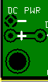
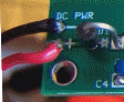
Sample Power Connection
PWR
To power the v9.0 receiver you will need a 9 volt to 12 volt DC source at a little over 100 mA. A supply that is free of ground connnections works best.
Use the conventional red/black wire for the power line +/- connections with the connector of your choice.
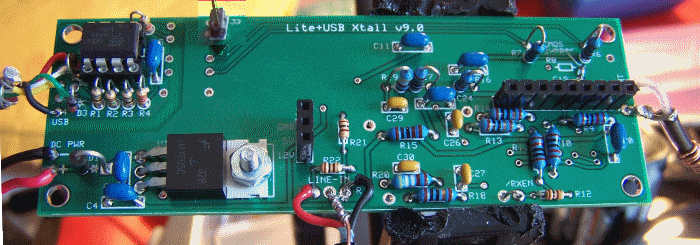
Completed Stage
Topside
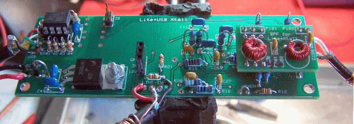
Board with BPF Daughter Board Plugged In
Testing
Note: This stage test requires you to have built and plugged in at least one bandpass filter.
The test assumes you have built an 80/40m BPF.
Current Draw (DMM)
Since you have just installed the various connections, it is a good idea to check the current draw one more time.
- Current numbers here are for the CMOS version of the Si570. You will need to adjust these up by about 14 mA for the LVDS version.
- Power the board up (author has been using an 11.6 Vdc battery pack)
- Measure the current draw and 5 V rail voltage with a 1K Ω limiting resistor
- Measure the current draw without the limiting resistor.
- Remove power
| Testpoint | Nominal Value | Author's | Yours |
|---|---|---|---|
| Current Limited mA | 6-10 mA | 7.5 mA | ______ |
| Current limited 5V rail | 1-2 Vdc | 971 mV | ______ |
| Non limited draw mA | 90-100 mA | 97.0 mA | ______ |
RX Test in Rocky
The ultimate test is to run Rocky, feeding the Ring and Tip outputs to the Line In inputs of your PC's sound card. You must have built at least one of the Bandpass Filter Boards (BPF) to conduct this test. The values below are appropriate for the 80/40m BPF Board.
- Follow this sequence to connect the board and the PC
(important note: there have been cases where this sequence was not followed
and damage to the board resulted)
- Plug the audio cable into your sound card's Line-In input
- Power up the board
- Plug the USB cable into the PC
- Run Rocky,
click the
File > Start Radiomenu choice, and click on theView > Settingsmenu - Click on the "Audio" Tab and select your sound card
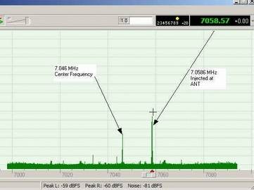
- Set Rocky's center frequency at 7.046 MHz (if it is not already selected) in the "I/Q Input Device" dropdown box).
- Click on OK to close the "Settings" Menu
- Set up your transceiver (or other signal source) to transmit a low power signal at 7.059 KHz into a dummy load and loosely couple it to the board with a short wire
- Click on Rocky's
File/Start Radio - You should see the Rocky spectrum display resembling the image above.
- If your signal source can sweep the frequency, observe Rocky's spectrum display as the generator sweeps through the "chunk" of bandwidth centered on the center frequency.
- If you see an unwanted "mirror image" of the desired signal, you may want to check out the image rejection hints on this website.