Description of Op-Amp Test Elmer Station

This station provides the facilities (clip leads, resistors, DMM) to the "Functional Test" at the end of the Op-Amps stage.
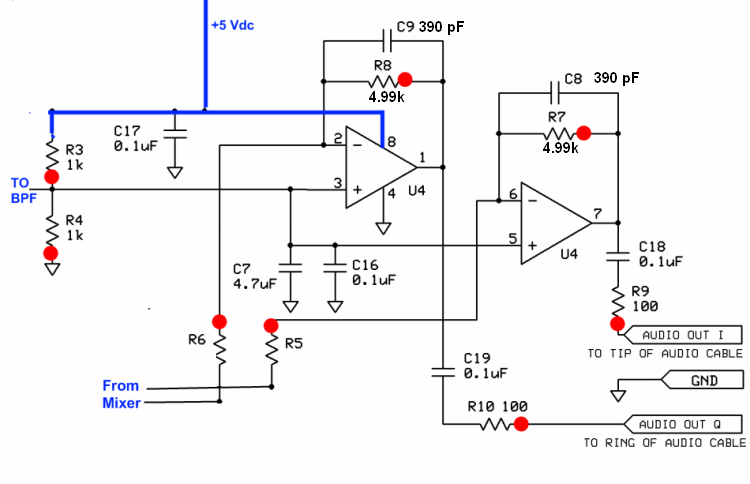
You will test the DC gain of each of the op-amps by connecting a 10k "bridging" resistor from each op-amp inverting input to circuit ground. This will introduce a test current equal to 2.5 /10k, which will be balanced by the current fed back from each op-amp's output through each 1k feedback resistor (R7 or R8). Each op-amp output will increase in voltage nominally by [2.5 *(4.99k + 10)]/10k (0r 1.25 Vdc) from the nominal DC level of 2.5 volts, yielding 3.75 Vdc.
Operational Amplifiers Schematic
(Resistor testpoints (hairpin, top, or left-hand lead), as physically installed on the board, are marked in the schematic with red dots). R7 and R8 are each 4.99kΩ

Resources
Supplies
| Item | Qty | Notes |
|---|---|---|
| 10k resistors with clip leads on each end | 4 | "bridging resistor |
| 9V battery | 1 | to power board under test |
| UNCOATED cookie sheet | 1 | (ESD protection) |
| ground wire | 1 | (for grounding cookie sheeet) |
Tools
(n/a)
Instruments
| Item | Qty | Notes |
|---|---|---|
| DMM | 1 | to measure op amp voltage output. COM lead should be cliplead. |
Process
Setup
Set the DMM to measure dc voltages in the 20V range
Detail Process

Verify Voltage Tests Performed
Prior to this test, the builder should have completed the OpAmp smoke test and then successfully measured the pin voltages onthe OpAmp chip, as described in their builder's manual. Verify that the builder has completed the voltage measurements for the Op-Amps.Ground the DMM and the Bridging Resistor:
- Clip the DMM's black ("COM") lead to the board ground (can use the ground wire on the board or the hairpin lead of R13 - near the crystal)
- Clip one lead of the 10k bridging resistor to the board ground
Power Up
Connect the board to the batteryTurn the DMM ON
Test Case "A"
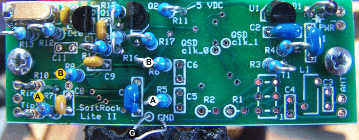
Clip the DMM's Red lead to R7 (Yellow "A")
-
Measure unbridged Voltages
DMM should read nominally 2.5 Vdc, typically 2.45 to 2.51Vdc. Bridge Ground to R5 (white "A")
Connect the free end of the 10k resistor to the hairpin lead of R5 (white dot "A" above)Measure Bridged Voltage
DMM should nominally read 3.75 Vdc, typically 2.67 to 3.76 Vdc
Test Case "B"
Clip the DMM's Red lead to R8 (Yellow "B")
-
Measure unbridged Voltages
DMM should read nominally 2.5 Vdc, typically 2.45 to 2.51Vdc. Bridge Ground to R6 (white "B")
Connect the free end of the 10k resistor to the hairpin lead of R5 (white dot "A" above)Measure Bridged Voltage
DMM should nominally read 3.75 Vdc, typically 2.67 to 3.76 Vdc
- Remove power and remove the bridging resistor and DMM clip leads
- Turn the DMM OFF
- If either reading is appreciably off the mark, send the builder with the recorded results to the troubleshooting/rework station
Results Table
| Test Case | Bridged? | Nominal Vdc | Typical Vdc |
|---|---|---|---|
| A (DMM to R7) | No | 2.5 | 2.45 - 2.51 |
| A (DMM to R7) | To R5 | 3.75 | 2.67 - 3.76 |
| B (DMM to R8) | No | 2.5 | 2.45 - 2.51 |
| B (DMM to R8) | To R6 | 3.75 | 2.67 - 3.76 |