Schematic
Theory of Operation
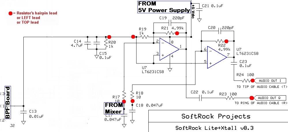
This stage amplifies the quadrature audio frequency difference products from the Mixer stage
via R17 and R18.
R19 and R20 make up a voltage divider that provides
the 2.5 Vdc bias to the Op-Amps, configured as an inverting amplifier. The ratios of
R21/R17 and R22/R18, respectively, determine the voltage gain of the output over the input
for each Op-Amp.
That voltage gain is theoretically 499:1, or about 54 dB. Each Op-Amp's output is
capacitively coupled through a 100 ohm resistor to the "Ring" (Q) and "Tip" (I)
Audio Out terminals for input to the PC's sound card.
Summary Build Steps
- Install SMT Capacitors (5)
- Install U7
- Install resistors (8)
- Install ceramic caps (5)
- Testing
Bill of Materials
| Designation | Component | Type | Qty | Notes |
|---|---|---|---|---|
| C13 | 0.01 µF | SMT 1206 | 1 | |
| C14 | 4.7 µF | ceramic | 1 | code 475 |
| C15 | 0.1 µF | SMT 1206 | 1 | |
| C17 | 0.047 µF | ceramic | 1 | code 473 |
| C18 | 0.047 µF | ceramic | 1 | code 473 |
| C19 | 220 pF | ceramic | 1 | code 221 |
| C20 | 220 pF | ceramic | 1 | code 221 |
| C21 | 0.1 µF | SMT 1206 | 1 | |
| C22 | 0.1 µF | SMT 1206 | 1 | |
| C23 | 0.1 µF | SMT 1206 | 1 | |
| R17 | 10 Ohm | Resistor 1% | 1 | hairpin (west-east) |
| R18 | 10 Ohm | Resistor 1% | 1 | hairpin (west-east) |
| R19 | 1k Ohm | Resistor 1% | 1 | Hairpin (south - North) |
| R20 | 1k Ohm | Resistor 1% | 1 | hairpin (east- west) |
| R21 | 4.99k Ohm | Resistor 1% | 1 | hairpin (east- west) |
| R22 | 4.99k Ohm | Resistor 1% | 1 | hairpin (east- west) |
| R23 | 100 Ohm | Resistor 1% | 1 | hairpin (north-south) |
| R24 | 100 Ohm | Resistor 1% | 1 | Hairpin (south - North) |
| U7 | LT6231 | SOIC-8 OpAmp | 1 | (bottom) |
| n/a | 5 µF | ceramic | 1 | blocking capacitor for audio test (not furnished with kit) |
Installation Notes
This stage mainly adds the amplification capabilities via the dual LT6231 Operational Amplifier, U7. The builder must take necessary ESD precautions. See the guidelines on installing SMT ICs.
Bottomside Components
(You may want to refer to the board bottom view)
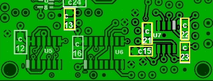
Install the SMT capacitors
- Install the 0.01 µF SMT cap, C13 (from the unmarked strip)
- Install the four 0.1 µF SMT caps:C15, C21-23 C (from the strip with the black marking).
| Check | Designation | Component | Type |
|---|---|---|---|
| C13 | 0.01 µF | SMT 1206 | |
| C15 | 0.1 µF | SMT 1206 (black-marked strip) | |
| C21 | 0.1 µF | SMT 1206 (black-marked strip) | |
| C22 | 0.1 µF | SMT 1206 (black-marked strip) | |
| C23 | 0.1 µF | SMT 1206 (black-marked strip) |
Install U7
(see notes on ESD precautions and SMT IC Installation)- Install U7, the LT6231 Operational Amplifier, on the bottom of the board
| Check | Designation | Component | Orientation |
|---|---|---|---|
| U7 | LT6231 |
SOIC-8 OpAmp 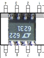
|
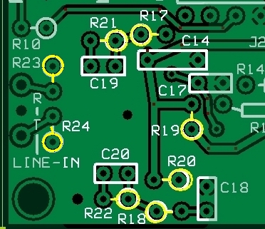
Topside Components
Install Resistors
- Install resistors R17-R24 (observe the correct "hairpin" orientation - see table below).
| Check | Designation | Component | Type | Component Orientation |
|---|---|---|---|---|
| R17 | 10 Ohm | Resistor 1% | hairpin (west-east) | |
| R18 | 10 Ohm | Resistor 1% | hairpin (west-east) | |
| R19 | 1k Ohm | Resistor 1% | Hairpin (south - North) | |
| R20 | 1k Ohm | Resistor 1% | hairpin (east- west) | |
| R21 | 4.99k Ohm | Resistor 1% | hairpin (east- west) | |
| R22 | 4.99k Ohm | Resistor 1% | hairpin (east- west) | |
| R23 | 100 Ohm | Resistor 1% | hairpin (north-south) | |
| R24 | 100 Ohm | Resistor 1% | Hairpin (south - North) |
Install Ceramic Caps
- Install the 5 ceramic capacitors (C14, C17-C20)
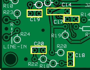
| Check | Designation | Component Value (code) | Type |
|---|---|---|---|
| C14 | 4.7 µF (code 475) | ceramic | |
| C17 | 0.047 µF (code 473) | ceramic | |
| C18 | 0.047 µF (code 473) | ceramic | |
| C19 | 220 pF (code 221) | ceramic | |
| C20 | 220 pF (code 221) | ceramic |
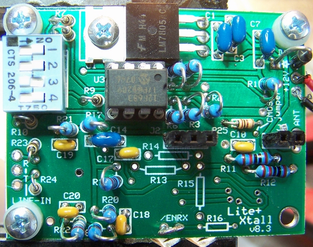
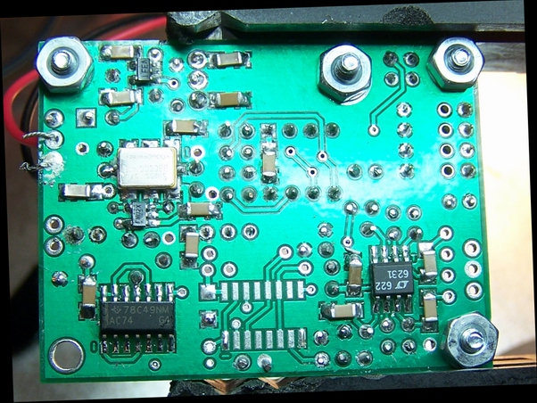
Completed Stage
Top
Bottom
Testing
Current Draw (DMM - 108 mA)
- Remember the 14 mA downward adjustment for the CMOS version of the Si570.
- Set SW1 for a center frequency of 7.046 MHz ("0100")
- Apply power and measure the current with your DVM's ma meter.
- The current draw on the LVDS version of the Si570 should be on the order of 107-108 mA
Current Limited Power Test
- Connect a 100 ohm resistor in series with the power line and apply 12 V dc power
- the current should be relatively low (around 10 mA or less)
- Measure the voltage WRT ground at the +5 V and at the 3.3 Vdc testpoints.
- A voltage of around 2 V dc on each testpoint indicates the power rails are not shorted
Voltage Divider R19/R20 (DMM - 2.5 Vdc)
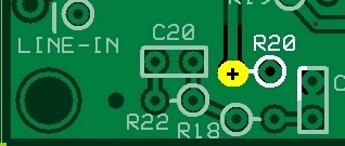
- Measure the voltage at the R20 hairpin lead with respect to ground.
- It should read approximately 2.5 Vdc (½ the 5 volt rail).
| Test Point | Units | Expected | Voltage as Measured |
|---|---|---|---|
| R20 hairpin lead | Vdc | 2.5 |
Pin Voltages (DMM - 5, 2.5, and 0 Vdc)
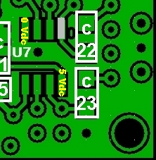
- Measure the voltages at the pins of U7.
- It is best to test for pin voltages at the actual pins (not the pads), thereby ensuring correct soldering of the pins to the pads.
| Test Point | Units | Expected | Pin Voltage(s) as Measured |
|---|---|---|---|
| U7, Pins 1, 2, 3, 5, 6 & 7 | Vdc | 2.5 | |
| U7, Pin 8 | Vdc | 5 | |
| U7, Pin 4 | Vdc | 0 |
OpAmp Test - DMM (No Scope)
Tony Parks suggested this next test for those who do not have an oscilloscope and/or audio frequency generator, since it requires only a DMM and some clip leads.
The test will test each of the two Op-Amps, but the steps described are for the second Op-Amp and involves R18 and R22. The test for the first Op-Amp involves, respectively, R17 and R21.
If the Op-Amp being tested is working, then the voltage measured at the output of the Op-Amp will increase to accomodate the effect of the changed bias on the input. Passing these tests gives you more than enough confidence to move on to the Mixer stage.
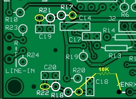
- Obtain a 10k resistor (or use the 10k resistor - R15 - that is to be installed in the next stage)
- using the DMM, measure the dc voltage with respect to ground at the hairpin of R22.
The result should be approximately 2.5 Vdc (½ the 5 Vdc rail). - keep the DMM lead on R22's hairpin
- Using two clip leads, "bridge" the 10k resistor between the hairpin of R18 and ground. See the diagram to the left.
- Observe the voltage reading at R22 hairpin. If OpAmp 1 is working, the voltage should have jumped to approximately 3.75 Vdc
- Remove the resistor/clip lead from R18 and the voltage at R22 should go back to the 2.5 Vdc level.
- Follow these same steps for OpAmp2, substituting R17 for R18 and R21 for R22.
Audio Injection
(optional)
(AF Oscillator/Scope/Freq Counter)
- Set up an audio signal generator for a low-level (10 mV p-p) output (you can use the output of IQGen or DQGen or Rocky's TX)
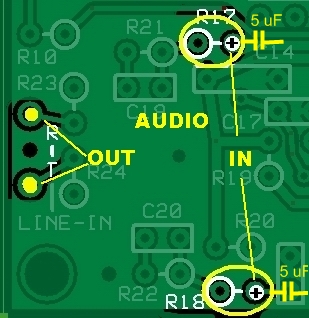
- Connect the audio generator's output, through a 5 µF dc blocking capacitor, to the hairpin lead of either R17 (for the "Q"/"Ring" Ouput) or R18 (for the "I"/"Tip" output)
- Connect the Scope's CH2 probe to the "Ring" or "Tip" output pad on the board
- Connect the Oscilloscope's CH1 probe to the audio generator's output
- Power up the board and adujust the amplitude of the input signal
- Measure the output. The gain should be on the order of 5 V p-p (54 dbB gain)
- Repeat the above steps for the other ("Tip" or "Ring") board output
Op-Amp In/Out
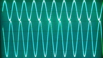
Courtesy of Leonard KC0WOX