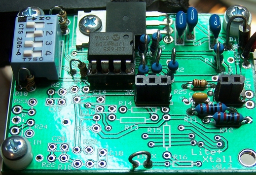
Schematic
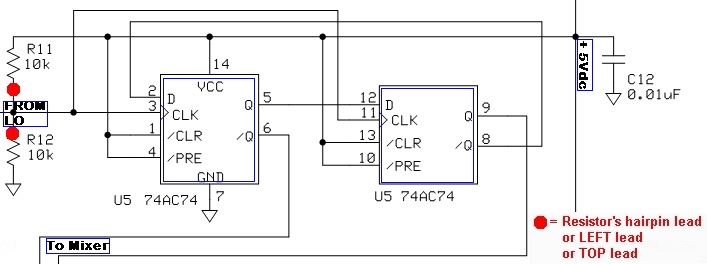
Theory of Operation
The Dividers stage takes in the local oscillator's signal and divides it by 4, producing two output signals. Each output signal is at a frequency that is ¼ the stage's input signal. The signals are "in quadrature", that is, they are 90° out of phase with each other. These are provided to the mixer stage as clocking signals to mix down the incoming "chunk" of RF.Summary Build Steps
- Install C12 and U5 on underside of board
- Install R11 and R12
- Testing
Bill of Materials
| Designation | Component | Type | Qty | Notes |
|---|---|---|---|---|
| C12 | 0.01 µF | SMT 1206 | 1 | (bottom) |
| R11 | 10k Ohm | Resistor 1% | 1 | flat |
| R12 | 10k Ohm | Resistor 1% | 1 | flat |
| U5 | 74AC74 | SOIC-14 SMT Dual FF | 1 | (bottom) |
Installation Notes
This stage mainly adds the frequency division and phase-shifting capabilities via the AC74 dual flip flop. The builder must take necessary ESD precautions. See the guidelines on installing SMT ICs.Bottomside Components
(You may want to refer to the board bottom view)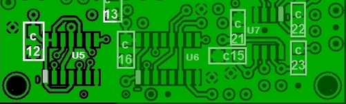
Install SMT Cap
See the guide for installing SMT Caps.- First, install the SMT by-pass cap, C12
- (C12 is one of the ten 0.01 µF SMT Caps provided in the kit)
| Check | Designation | Component |
|---|---|---|
| C12 | 0.01 µF |
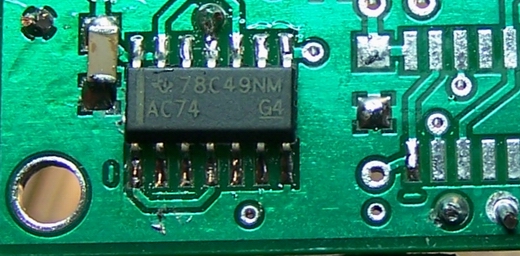
Install The AC74 SMT IC, U5
See the guide for installing SMT ICs.Note, also, that
ESD Precautions are in order here.
- Install IC U5.
- See table below for orientation
| Check | Designation | Component | Orientation |
|---|---|---|---|
| U5 | 74AC74 | 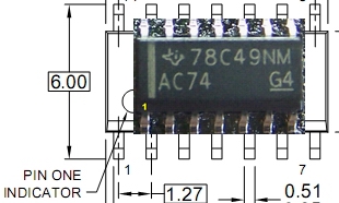
|
Topside Components
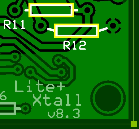
Install the 2 Resistors
See guide for installing resistors.
- Install the two resistors (R11 and R12) that provide the voltage divider for the IC.
| Check | Designation | Component | Orientation |
|---|---|---|---|
| R11 | 10k Ohm | Flat | |
| R12 | 10k Ohm | Flat |
Completed Board
Top Side
Bottom Side
Testing
Current Draw(DMM - 98.4 mA)
- Current numbers here are for the LVDS version of the Si570. You will need to adjust these down by about 14 mA forr the CMOS version.
- Set SW1 to "0100", apply power, and measure the current with your DVM's mA meter.
- The current draw should be around 98 mA
Current Limited Power Test
- Connect a 100 ohm resistor in series with the power line and apply 12 V dc power
- the current should be relatively low (around 10 mA or less)
- Measure the voltage WRT ground at the +5 V and at the 3.3 Vdc testpoints.
- A voltage of around 2 V dc on each testpoint indicates the power rails are not shorted
Voltage Tests (DMM - 2.5 Vdc)
If the output of the dividers are not as expected, check the voltages at the pins of U5. Unexpected values here usually point to problems with soldering U5 and/or the voltage dividing resistors R11 and R12.Using a DMM:
- Measure the output of the voltage divider with respect to ground. Measure at the left-hand lead of either R11 or R12 This should yield approximately ½ the 5 volt rail voltage.
- Measure the voltages (with respect to ground) on the pins of U5. It is best to test for these voltages at the actual pins (not the pads), thereby ensuring correct soldering of the pins to the pads.
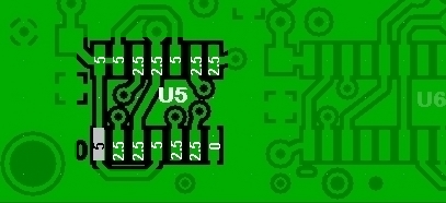
| Test Point | Units | Expected | As Actually Measured (Power ON) |
|---|---|---|---|
| (topside) left-hand lead of R11 or R12 | Vdc | 2.5 (½ the 5 volt rail) | |
| U5, Pins 1, 4, 10, 13, 14 | Vdc | 5 | |
| U5, Pins 2, 3, 5, 6, 8, 9, 11, 12 | Vdc | 2.5 (½ the 5 volt rail) | |
| U5, Pin 7 | Vdc | 0 |
Test Center Frequency Output
- Connect a short piece of wire as an "antenna" for your HF RX and lay it over the board
- Tune the LO to a center frequency of 7.046 MHz (SW1 = "0100")
- Apply power to the board
- Tune your radio to find the signal at 7.046 MHz
- If you can detect the signal and have passed the voltage tests above, your divider stage is pretty well assured to be working correctly.
- If there is no signal at this point,
and you have successfully passed the previous stage's tests,
check the intersections of the two stages (depending upon Si570 version):
- If LVDC: Check U8, R25, and C10 connections/soldering (
- If CMOS: Check the CMOPS jumper and C10 connections/soldering
U5 Output (Optional Test)
In the unlikely event that you have or have access to a dual channel oscilloscope, you can test the divider outputs here.
Do not attempt these measurements unless your scope is a good quality, calibrated scope with correctly compensated probes. A lower quality scope will result in wildly variant measurements of voltages and waveforms.
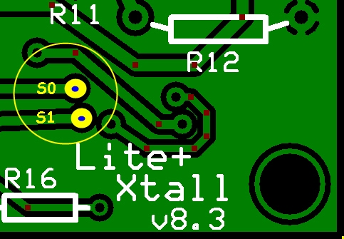
U5 sends I and Q signals to the mixer's S0 and S1 inputs.
- Use a dual channel oscilloscoipe, triggering on Channel 1, and
- measure the S0 and S1 outputs at the corresponding testpoints on the top side of the board, as indicated above.
- They should both be the same frequency (¼ of the LO Output - assuming you use the SW 1 settings from the LO test, that would be 7.046 mHz) and should be in quadrature (90° out of phase with each other). The above image shows approximations of p-p voltages and frequencies of the 2 quadrature signals.
- They should be approximately 5 volt p-p square waves. The square waves may have a fair amount of ringing on them depending a bit on your scope connection to the circuit board (see Waveforms below).
Divider Output Waveforms (Quadrature, 7.046 MHz)
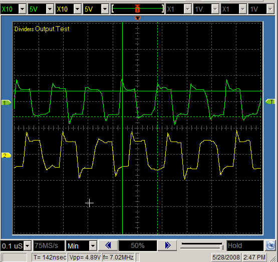
Note: author's scope lacks the quality suggested above.