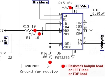
Schematic
Theory of Operation
The mixer stage acts like two traditional direct conversion mixers operating in tandem. Each takes in half of the filtered RF from the bandpass filter stage and one of the quadrature center frequency signals, then "mixes" them to with an output being the traditional mixer products, in this case, two audio frequency signals that represent the difference between the two inputs (RF and Local Oscillator). These two signals are referred to as the I (in-phase) and Q (Quadrature) signals and are fed into the high gain Op-Amps stage for amplification and delivery to the audio outputs (and, thence, to the PC's sound card). Resistors R15 and R16 form a voltage divider to produce approximately 50 mV dc at pins 1 and 15 to enable the mixer's operation.
Summary Build Steps
- Install SMT cap C16
- Install U6
- Install resistors (4)
- Install ground/ENRX (if not already done)
- Testing
Bill of Materials
| Designation | Component | Type | Qty | Notes |
|---|---|---|---|---|
| C16 | 0.01 µF | SMT 1206 | 1 | |
| R13 | 10 Ohm | Resistor 1% | 1 | flat |
| R14 | 10 Ohm | Resistor 1% | 1 | flat |
| R15 | 10k Ohm | Resistor 1% | 1 | flat |
| R16 | 100 Ohm | Resistor 1% | 1 | flat |
| U6 | FST3253MX | SOIC-14 SMT Mixer | 1 | (bottom) |
Installation Notes
Bottomside Components
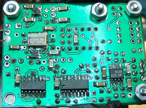
(You may want to refer to the board bottom view)
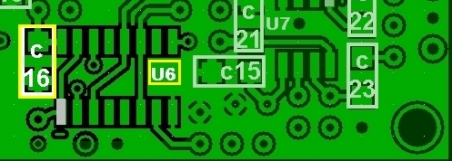
Install C16 (SMT)
(see SMT Cap installation guide)- Install the .01 uF SMT Cap (C16 - from the unmarked strip) to the bottom side of the board
| Check | Designation | Component | Type |
|---|---|---|---|
| C16 | 0.01 µF | SMT 1206 |
Install U6
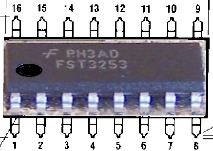
Follow the guidelines for ESD precautions and SMT IC Installation.- Install U61, the FST3253 Switch (Mixer), to the bottom side of the board on the 14 SOIC pads provided.
- The IC is oriented such that when the dot/depression on the top is on the left hand side, pin 1 is at the bottom left (see table below).
| Check | Designation | Component | Orientation |
|---|---|---|---|
| U6 | FST3253MX SOIC-16 SMT Mixer |
|
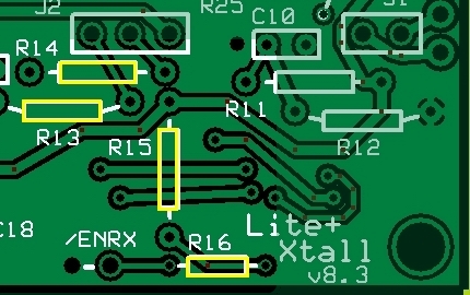
Topside Components
Install the 4 resistors
- Install resistors R13-R16 to the top side of the board (all are "flat" orientation)
| Check | Designation | Component | Orientation |
|---|---|---|---|
| R13 | 10 Ohm | Flat | |
| R14 | 10 Ohm | Flat | |
| R15 | 10k Ohm | Flat | |
| R16 | 100 Ohm | Flat |
Ground /ENRX
If you have not already done so, install the /ENRX loop (see instructions in the Power Supply Stage)Completed Stage
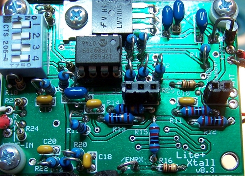
Top Side
Bottom Side
Testing
Note: these tests require you to have built and plugged in at least one bandpass filters.
If you have not yet done so, you can still conduct the current and voltage tests provided you short pins 1, 2, and 3 of J2 together to provide the DC equivalent of the T100 secondaries.
Current Draw (DMM - 109 mA)
- Remember the -14 mA adjustment fot the CMOS version.
- Measure the current with your DVM's ma meter.
- The current draw should be on the around 110 mA
Current Limited Power Test
- Connect a 100 ohm resistor in series with the power line and apply 12 V dc power
- the current should be relatively low (around 10 mA or less)
- Measure the voltage WRT ground at the +5 V and at the 3.3 Vdc testpoints.
- A voltage of around 2 V dc on each testpoint indicates the power rails are not shorted
Pin Voltages (DMM - 0, 2.5, and 5 Vdc)
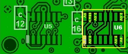
Measure U6 Pin Voltages
- Using a DMM, measure the dc voltage (with respect to ground) of the pins of U6.
- It is best to test for these voltages at the actual pins (not the pads), thereby ensuring correct soldering of the pins to the pads.
| Test Point | Units | Expected | Measured | Circuit |
|---|---|---|---|---|
| U6, Pin 8 | Vdc | 0 | Mixer | |
| U6, Pin 16 | Vdc | 5 | Mixer | |
| U6, Pins 1&15 | mVdc | 50 | Mixer | |
| U6, Pin 2 | Vdc | 2.5 | Mixer | |
| U6, Pin 14 | Vdc | 2.5 | Mixer | |
| U6, Pin 7 | Vdc | 2.5 | Mixer | |
| U6, Pin 9 | Vdc | 2.5 | Mixer |
If the voltage at pins 1 and 15 is not in the area of 50 mV, then the mixer will not be enabled and there will be no outputs at pins 7 and 9.
If you see a high (~5 Vdc) voltage at pins 1 and 15, check your ENRX
RX Test in Rocky
The ultimate test is to run Rocky, feeding the Ring and Tip outputs to the Line In inputs of your PC's sound card.
- If you already have not done so, download and install Rocky
- Run Rocky and click on the
View > Settingsmenu - In the "settings" menu, click on the "DSP" tab
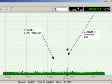
- in the "DSP" tab's "Local Oscillator" section, click on the button marked "Single Band" and type in the desired center frequency (7046000). This sets Rocky's center frequency at 7.046 MHz.
- Click on the "Audio" Tab and select your sound card (if it is not already selected) in the "I/Q Input Device" dropdown box.
- Click on OK to close the "Settings" Menu
- Plug the audio cable into your sound card's Line-In input
- Set up your transceiver (or other signal source) to transmit a low power signal at 7.059 KHz into a dummy load and loosely couple it to the board with a short wire
- With RF signal (e.g. 7.059 MHz) transmitting, Power up the board
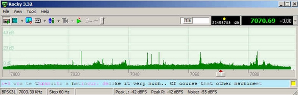
and click the
File > Start Radiomenu choice. - You should see the Rocky spectrum display resembling the image above.
- If your signal source can sweep the frequency, observe Rocky's spectrum display as the generator sweeps through the "chunk" of bandwidth centered on the center frequency.
- If you see an unwanted "mirror image" of the desired signal, you may want to check out the image rejection hints on this website.
RF Injection (optional)
(RF Signal Generator/Scope/Freq Counter)
You must have built at least one of the Bandpass Filter Boards (BPF) to conduct this test.
- Mount the BPF board onto the pins for J1 and J2
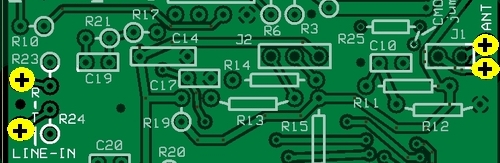
- Inject an RF signal of about 10 mV RMS at the ANT and RTN pads on the right side on the main board. The signal should be a few kHz either side of the selected center frequency (e.g., inject a 7.059 MHz signal for a center frequency of 7.046 MHz.
- Look for the output at the R (ring) and T (tip) pads on the left side of the main board. It should be an audio frequency representing the difference between the injected signal and the selected center frequency and it should be approximately 5 V p-p.
Misc Hardware
You will need to connect your finished board to the outside world. The following components are recommended:Audio (I/Q) Connection
LINE IN
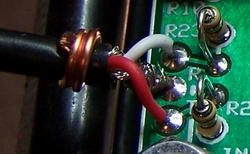
(the Ring and Tip audio outputs of the board)Depending upon your ultimate enclosure/mounting requirements, you want to connect these three pads to good quality shielded 2 conductor audio cable, terminated either by a 3.5 mm mini plug or a mini jack.
Use a short length of solid hookup wire, soldered to the shielding and to the ground/common connection, and wrapped firmly around the outer insulation of the cable as a strain relief mechanism.
Antenna Connection
ANT/RET
Use RG-174U 50 ohm "micro" coax for the antenna connection, There is a good discussion of RG-174 coax and techniques for installing connectors available on the internet.
Power Connection
PWR
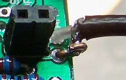
Use the conventional red/black wire for the power line +/- connections with the connector of your choice
The Final Test
Once the mixer tests are completed and the extra hardware is installed, you are ready to take the radio for a spin. This final test will use Rocky as the SDR Software. This test assumes you have the following:- A Windows Computer on which Rocky has been installed.
- A sound card with a stereo input ("mic" or "Line-In")
- An antenna (the better the impedance match to 50 ohms, the better the reception)
Setup the Radio and the PC
- Plug the audio output cable into the "mic" or "Line-In" input on the PC's sound card.
- Connect the antenna cable to your antenna (you can use a simle wire antenna, but the reception will be poor).
- Copy the 16 bands into Rocky's INI file (see instructions in SW1 Settings page)
- "Dial in" the desired frequency on SW1 (see SW1 Settings) - example here uses "0100" for a center frequency of 7.046 MHz
- Set up Rocky for RX:
- Run Rocky
- Select the desired center frequency from the multiband dropdown boxin the upper right hand corner of Rocky's screen
- If you have more than one soundcard, make sure Rocky is using the right soundcard
(View > Settings > Audio)
It's alive, alive I tell you!
- Apply power to the receiver
- If not already done, start the Rocky "radio"
(File > Start Radio)
A few notes from the reflector
- Changing frequencies while powered up: there should be no problem in changing the center frequencies, within a given BPF's range, while the rig os powered up
- however, it is advisable to change BPF boards only when power is OFF.