Power Bus Introduction
General
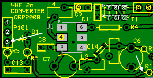
This first phase of the build simply installs and tests the dc power bus for the board. The board draws its power from the 12 Vdc present at pin 3 of J2 on the Lite + Xtall RX V9.0 receiver board, via pin 3 of P101 on the converter board.
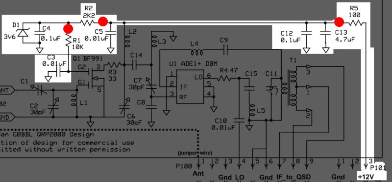
The zener diode D1 clamps the input voltage to 3.6V.
Power Bus Schematic
(Resistor testpoints (hairpin, top, or left-hand lead), as physically installed on the board, are marked in the schematic with red dots)
(Click for Full Schematic)
Power Bus Bill of Materials
Stage Bill of Materials
(resistor images and color codes courtesy of WIlfried, DL5SWB's R-Color Code program)
| Check | Designation | Component | Marking | Category | Orientation | Notes | Circuit |
|---|---|---|---|---|---|---|---|
| ❏ | C03 | 0.01 uF | (smt)
 | SMT 1206 | pads shaded yellow | Power Bus | |
| ❏ | C13 | 4.7 uF 10% | 475
 | Ceramic | Power Bus | ||
| ❏ | D1 | 1N5227B | 1N5227B | Axial | Install D1 with the banded end to the square hole. | Power Bus | |
| ❏ | C05 | 0.01 uF | (smt)
 | SMT 1206 | pads shaded yellow | Power Bus | |
| ❏ | C04 | 0.1 uF | (smt) black stripe
 | SMT 1206 | pads shaded white | Power Bus | |
| ❏ | R1 | 10 k 1/6W 5% | brn-blk-ora-gld
 | 1/6W | E-W | Power Bus | |
| ❏ | C12 | 0.1 uF | (smt) black stripe
 | SMT 1206 | pads shaded white | Power Bus | |
| ❏ | R2 | 2.2 k 1/6W 5% | r-r-r-gld
 | 1/6W | N-S | Power Bus | |
| ❏ | R5 | 100 1/6W 5% | br-blk-br-gld
 | 1/6W | N-S | Power Bus |
Power Bus Summary Build Notes
- Install SMT Capacitors
- Install Topside Components
- Test the Stage
Power Bus Detailed Build Notes
Bottom of the Board

Install SMT Capacitors
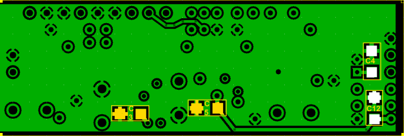
Install the four SMT capacitors as indicated in the picture of the board bottom. The cap pads are shaded white for 0.1 uF (in black striped strip) and yellow for the 0.01 uF (in clear strip) caps.
Once they are installed, you might want to test each to be sure there is no short across them.
| Check | Designation | Component | Marking | Category | Orientation | Notes |
|---|---|---|---|---|---|---|
| ❏ | C03 | 0.01 uF | (smt)
 | SMT 1206 | pads shaded yellow | |
| ❏ | C05 | 0.01 uF | (smt)
 | SMT 1206 | pads shaded yellow | |
| ❏ | C04 | 0.1 uF | (smt) black stripe
 | SMT 1206 | pads shaded white | |
| ❏ | C12 | 0.1 uF | (smt) black stripe
 | SMT 1206 | pads shaded white |
Top of the Board

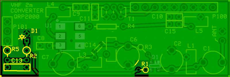
Install Topside Components
| Check | Designation | Component | Marking | Category | Orientation | Notes |
|---|---|---|---|---|---|---|
| ❏ | C13 | 4.7 uF 10% | 475
 | Ceramic | ||
| ❏ | D1 | 1N5227B | 1N5227B | Axial | Install D1 with the banded end to the square hole. | |
| ❏ | R1 | 10 k 1/6W 5% | brn-blk-ora-gld
 | 1/6W | E-W | |
| ❏ | R2 | 2.2 k 1/6W 5% | r-r-r-gld
 | 1/6W | N-S | |
| ❏ | R5 | 100 1/6W 5% | br-blk-br-gld
 | 1/6W | N-S |
Power Bus Testing
Voltage Test
Test Setup
Apply 12 Vdc to pin 3 of P101 and measure the voltage at the hairpin of R1
You should see between 2.8 and 3.1 Vdc
"The diode should not really start conducting until the zener point has been exceeded, i.e. around 3.6v. I just checked on my converters here and sure enough the voltage on R1 is low, around 2.8v on mine. It's something I would not usually bother measuring, no point really as it is only a 'simple' circuit, and the converter performed very well under testing. On closer inspection, I see the zener diode Tony has supplied with the kits is the 1N5xxx series one. That was the same type supplied with the USB interface and had very strange characteristics, appearing to 'zener' at a much lower voltage than specified. "

Test Measurements
| Testpoint | Units | Nominal Value | Author's | Yours |
|---|---|---|---|---|
| hairpin lead of R1 | Vdc | 3 | tbd | _______ |