Remainder Introduction
General
This phase completes the installation of the kit's components.
Some of the capacitors are band-specific items and their values will depend on which version of the converter you are building (6m, 4m, or 2m). In the installation tasks below, the band-specific items are separated out into band-specific "Bill of Material" (BOM) pages for your convnience.
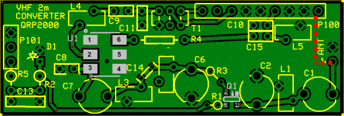
Remainder Schematic
(Resistor testpoints (hairpin, top, or left-hand lead), as physically installed on the board, are marked in the schematic with red dots)
(Click for Full Schematic)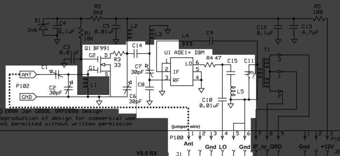
Remainder Bill of Materials
Stage Bill of Materials
(resistor images and color codes courtesy of WIlfried, DL5SWB's R-Color Code program)
| Check | Designation | Component | Marking | Category | Orientation | Notes | Circuit |
|---|---|---|---|---|---|---|---|
| ❏ | P101 | header, 3-pin |
 | header | Remainder | ||
| ❏ | P100 | header, 9-pin |
 | header | Remainder | ||
| ❏ | C01 | band-specific | misc | Remainder | |||
| ❏ | C08 | band-specific | misc | Remainder | |||
| ❏ | Q1 | BF991 SMT Dual-Gate MOSFET |
| SOT-143 | Remainder | ||
| ❏ | C09 | band-specific | misc | Remainder | |||
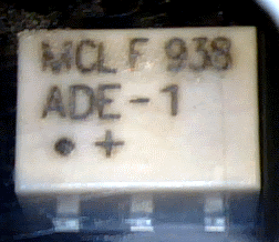
| ❏ | U1 | ADM +DB Double-balancede Mixer | ADE
 | SMT Mixer | Remainder | ||
| ❏ | C02 | trimmer capacitor 30 pF | green
 | trimmer | Remainder | ||
| ❏ | C06 | trimmer capacitor 30 pF | green
| trimmer | Remainder | ||
| ❏ | C10 | 10 nF (.01uF) | 103
 | Ceramic | Remainder | ||
| ❏ | C11 | band-specific | misc | Remainder | |||
| ❏ | C07 | trimmer capacitor 30 pF | green
| trimmer | Remainder | ||
| ❏ | C14 | band-specific | misc | Remainder | |||
| ❏ | R3 | 33 1/6W 5% | ora-ora-blk-gld
 | 1/6W | NW-SE | Remainder | |
| ❏ | R4 | 47 1/6W 5% | yel-vio-blk-gld
 | 1/6W | flat-horiz | Remainder | |
| ❏ | jumper | misc hookup wire | misc | Remainder | |||
| ❏ | C15 | unused capacitor | unused | C15 is unused in current design | Remainder |
Band Specific Items for 6m Band
| Check | Designation | Component | Marking | Category | Orientation | Notes | Circuit |
|---|---|---|---|---|---|---|---|
| ❏ | C01 | trimmer capacitor 30 pF | green
| trimmer | Remainder | ||
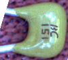
| ❏ | C08 | 150 pF 5% | 151
 | Ceramic | Remainder | ||
| ❏ | C09 | 180 pF 5% | 181
 | Ceramic | Remainder | ||
| ❏ | C11 | 220 pF 5% | 221 | Ceramic | Remainder | ||
| ❏ | C14 | 2.7 pF | 2.7J | Ceramic | Remainder |
Band Specific Items for 4m Band
| Check | Designation | Component | Marking | Category | Orientation | Notes | Circuit |
|---|---|---|---|---|---|---|---|
| ❏ | C01 | trimmer capacitor 30 pF | green
| trimmer | Remainder | ||
| ❏ | C08 | 120 pF 5% | 121 | Ceramic | Not furnished with kit | Remainder | |
| ❏ | C09 | 82 pF | 82J
 | Ceramic | Remainder | ||
| ❏ | C11 | 270 pF 5% | 271 | Ceramic | Remainder | ||
| ❏ | C14 | 2.2 pF | 2.2 | Ceramic | Not furnished with kit | Remainder |
Band Specific Items for 2m Band
| Check | Designation | Component | Marking | Category | Orientation | Notes | Circuit |
|---|---|---|---|---|---|---|---|
| ❏ | C01 | trimmer capacitor 10 pF | white
 | trimmer | Remainder | ||
| ❏ | C08 | 100 pF 5% | 101
 | Ceramic | Remainder | ||
| ❏ | C09 | 82 pF | 82J
| Ceramic | Remainder | ||
| ❏ | C11 | 270 pF 5% | 271 | Ceramic | Remainder | ||
| ❏ | C14 | 1.2 pF | 1.2
 | Ceramic | Remainder |
Remainder Summary Build Notes
- Install Headers for P100 and P101
- Install U1 and Q1
- Install Trimmer Capacitors
- Install Ceramics and Resistors
- Test the Stage
Remainder Detailed Build Notes
Top of the Board
Install Headers for P100 and P101
Install the two headers (9 pin P100 and 3 pin P101) to the underside of the board, such that the longer ends of the pins are protruding from the underside so as to mate with the jacks on the RX V9.0 board. It may be helpful to use those V9.0 jacks as a "jig" for ensuring that the pins will fit once soldered to the converter board.

| Check | Designation | Component | Marking | Category | Orientation | Notes |
|---|---|---|---|---|---|---|
| ❏ | P101 | header, 3-pin |
| header | ||
| ❏ | P100 | header, 9-pin |
| header |
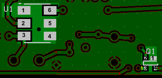
Install U1 and Q1
Install the SMT devices U1 and Q1. Take ESD precautions and take care to avoid solder splashes, especially in soldering Q1 to its 4 pads.
| Check | Designation | Component | Marking | Category | Orientation | Notes |
|---|---|---|---|---|---|---|
| ❏ | Q1 | BF991 SMT Dual-Gate MOSFET |
| SOT-143 | ||
| ❏ | U1 | ADM +DB Double-balancede Mixer | ADE
| SMT Mixer | Take ESD precautions |
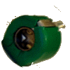
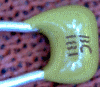
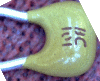
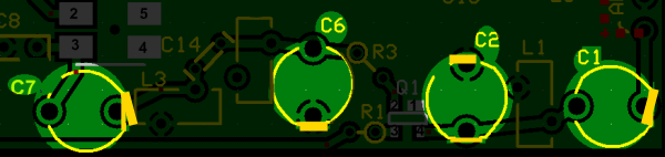
Install Trimmer Capacitors
Install the four trimmer capacitors (Note: trimmer C01 is band-specific)
Orient the trimmer capacitors' flat spot to the corresponding flat spot on the silkscreen.
| Check | Designation | Component | Marking | Category | Orientation | Notes |
|---|---|---|---|---|---|---|
| ❏ | C01 | band-specific | misc | |||
| ❏ | C02 | trimmer capacitor 30 pF | green
| trimmer | ||
| ❏ | C06 | trimmer capacitor 30 pF | green
| trimmer | ||
| ❏ | C07 | trimmer capacitor 30 pF | green
| trimmer |
| Check | Band | Designation | Component | Marking | Category | Orientation | Notes |
|---|---|---|---|---|---|---|---|
| ❏ | 6m | C01 | trimmer capacitor 30 pF | green
| trimmer | ||
| ❏ | 4m | C01 | trimmer capacitor 30 pF | green
| trimmer | ||
| ❏ | 2m | C01 | trimmer capacitor 10 pF | white
| trimmer |
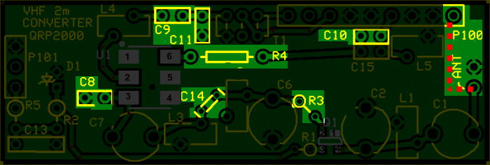
Install Ceramics and Resistors
Finally, install the ceramic capacitors and the last two resistors.
Optionally, you may want to install a jumper wire between the ANT lead and Pin 1 of P100 (see the dotted red line on the graphic of the board top).
Note: C15 has been removed from the current design in all of its manifestations and is neither required not provided.
| Check | Designation | Component | Marking | Category | Orientation | Notes |
|---|---|---|---|---|---|---|
| ❏ | C08 | band-specific | misc | |||
| ❏ | C09 | band-specific | misc | |||
| ❏ | C10 | 10 nF (.01uF) | 103
| Ceramic | ||
| ❏ | C11 | band-specific | misc | |||
| ❏ | C14 | band-specific | misc | |||
| ❏ | R3 | 33 1/6W 5% | ora-ora-blk-gld
| 1/6W | NW-SE | |
| ❏ | R4 | 47 1/6W 5% | yel-vio-blk-gld
| 1/6W | flat-horiz | |
| ❏ | jumper | misc hookup wire | misc | |||
| ❏ | C15 | unused capacitor | unused | C15 is unused in current design |
| Check | Band | Designation | Component | Marking | Category | Orientation | Notes |
|---|---|---|---|---|---|---|---|
| ❏ | 6m | C14 | 2.7 pF | 2.7J | Ceramic | ||
| ❏ | 6m | C11 | 220 pF 5% | 221 | Ceramic | ||
| ❏ | 6m | C09 | 180 pF 5% | 181
| Ceramic | ||
| ❏ | 6m | C08 | 150 pF 5% | 151
| Ceramic | ||
| ❏ | 4m | C14 | 2.2 pF | 2.2 | Ceramic | Not furnished with kit | |
| ❏ | 4m | C11 | 270 pF 5% | 271 | Ceramic | ||
| ❏ | 4m | C09 | 82 pF | 82J
| Ceramic | ||
| ❏ | 4m | C08 | 120 pF 5% | 121 | Ceramic | Not furnished with kit | |
| ❏ | 2m | C14 | 1.2 pF | 1.2
| Ceramic | ||
| ❏ | 2m | C11 | 270 pF 5% | 271 | Ceramic | ||
| ❏ | 2m | C09 | 82 pF | 82J
| Ceramic | ||
| ❏ | 2m | C08 | 100 pF 5% | 101
| Ceramic |
Remainder Testing
Setup for Tests and Adjustment
Test Setup
Thanks to Bob G8VOI for much of the info contained in this section.
When it comes to doing the final test and aligning the converter, the easiest program to use would be Rocky, as it is possible to edit the Rocky.ini file and put in the appropriate center frequencies for 50.xxxx, 70.xxxx or 144.xxxxMHz directly in it.
The biggest hurdle at this point is setting up the AVR firmware, again the set up needed for Rocky is one of the simplest ones, unlike PSDR or some versions of Winrad.
It is highly recommended for anyone wanting to use the VHF converters to obtain and use a minimum of v15.11, or the newest v15.12 firmware for the AVR chip on the V9.0. Both can be configured to work with all vailable SDR programs.
Ensure you have the Correct AVR Firmware
If your AVR chip does not have version 15.12 of the firmware, then you must obtain one that does. You can get one from Cecil K5NWA at http://www.softrockradio.org/catalog/32/microcontrollers (be sure to specify:
chip type=ATiny85 and
firmware version = 15.12)Obtain and Install CFGSR
Download and install the CFGSR Firmware Configuration Software from Fred PE0FKO's site: CFGSR.EXE and
SRDLL.dllConfigure the AVR Firmware using CFGSR
Refer to Bob G8VOI's users manual for this configuration. The manual was written for configuration of the AVR chip using Winrad as the User Interface; the procedures, however, apply just as well for Fred's new CFGSR User Interface. One notable exception is the Si570 device address: in the Winrad UI, it is 85 (decimal); in CFGSR UI it is 55 (hexadecimal equivalent of 85 decimal).Set up Rocky
- Download, unzip, and install Rocky software from Rocky Website
- Edit/replaceoRicky.INI file with entries for desired frequencies
The following table shows what occurs "behind the curtain" when you set up the Rocky.ini file fow a center frequency of 146.52MHz. If you have previously programmed the 0.8 multiplier into the AVR in the above steps, then everything happens automatically:
Event Result Units (1.) Rocky.ini file entry "146.520_MHz=146520000" (2.) Causes Rocky Spectrum Center Freq Display as 146.520 MHz (3.) Rocky Multiplies the Center Frequency by 4 and Sends to AVR 586,080,000 Hz (4.) AVR "undoes" the divide by 4, multiplies the result by .8 and Sends to Si570 117,216,000 Hz (5.) Si570 Oscillates at 117,216,000 Hz (6.) Dividers Produce 29,304,000 Hz (7.) Converter Receives Antenna Signal on 146,540,000 Hz (8.) Converter Mixer Produces IF of 29,324,000 Hz (9.) V9.0 Mixer Produces IF of 20,000 Hz (10.) Rocky Displays Received signal at 146.540 MHz (You may wish to review the Theory of Operation section on the home page to see graphically what happens "behind the curtains".
Plug board into V9.0
Connect up the V9.0 RX board to the PC (antenna, audio, and USB cables). Plug the Converter board into jacks J1 and J2. Start up Rocky and select a frequency.
Set Up Signal Source
The ideal situation is to use a signal generator to produce a stable signal source to carry out the alignment with, but failing that it can be done with an off air signal such as a beacon or repeater. Using the signal source, tune it to a frequency either side of the selected center frequency.
Sometimes stages like the RF amplifier Q1 can go unstable if it sees a 'strange' load on it's input, so it is good practice to use a 50 ohm attenuator on the input during alignment to ensure it 'sees' a good resistive load, something like 3 or 6dB pad is sufficient. Of course in real life attached to an aerial, conditions will change and the input trimmers might require a slight tweak if there are signs of instability.
Adjust Trimmer Caps
Using Rocky, and a known signal, alignment is simply a case of going through the 4 trimmer capacitors in turn from the input and adjusting for maximum signal. You will also see a smooth increase in the noise floor level as it is optimised. The temptation is to tune for 'maximum smoke', but those are often the conditions which lead to instability, and therefore it's wiser to back things off a fraction to ensure reliable operation. In practice the small loss of performance sacrificed is not noticeable.