Kit Contents
Here is the kit as received.
Bill of Materials
The kit comes in 2 bags: one for all of the BPF boards and one for the main board. The kit the author built did not come with the U4, SI570. That was ordered separately.
Kit Contents
The v8.3 kits are sorted into four small zip-loc bags. One bag contains the circuit
board and the packet of
ICs.
The four BPF module kits are together in a zip-loc bag. Included with the
BPF kits is a 9-pin length of a SIP pin strip. This
pin strip is to be used as a tool to align the 2-pin and 3-pin sections of the
header sockets on the v8.3 main circuit board. Afterwards
the 9-pin header strip may be snipped into 2-pin or 3-pin lengths as spares for the
pins
that mount on the bottom of each BPF board.
Withn the main board bag is a pink anti-static IC bag containing the two SOT23-5 ICs (FIN1002 and LP2992AIM5-3.3) and the 74AC74, FST3253 and LT6231 The two SOT235 ICs are rolled up in the bottom half of the pink anti-static bag. There are two staples through the bag that provide an upper compartment for the three SOIC parts and a lower compartment for the two SOT23-5 parts. First remove the staple that allow the SOIC parts to be removed and then remove the second staple to get to the SOT23-5 parts. Abbreviated markings on the top of the FIN1002 IC indicate that it is the FIN1002.
The third and fourth zip-loc bags in the kit include the resistor/capacitor bag
and a hardware bag. Included in the resistor/capacitor bag is an anti-static bag
holding the programmed PIC (U3), the PIC socket, the DIP switch (SW1), and the 5
volts LM7805 TO-220 cased regulator IC (U1).
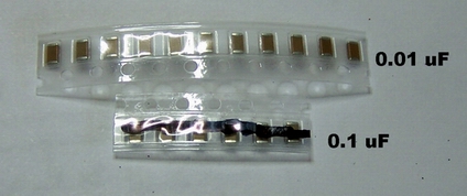
Caveat: Note that the SMT caps come in two different strips: there are 5 SMT caps (black stripe on strip) that are 0.1 µF (6 are shipped with the kit); there are 10 SMT caps (unmarked strip) that are 0.01 µF (11 are shipped with the kit). Do not get them mixed up.
Here is a list of passive components (resistors and capacitors), grouped by quantity, to facilitate inventorying. Thanks to Pete N4ZR for suggesting this:
| Resistors | QTY |
|---|---|
| 10Ohm | 4 |
| 100 Ohm | 8 |
| 1kOhm | 4 |
| 4.99k Ohm | 2 |
| 10k Ohm | 7 |
| Caps | QTY |
|---|---|
| 82 pF (code 82) | 1 |
| 180 pF (code 181) | 1 |
| 220 pF (code 221) | 3 |
| 330 pF (code 331 | 1 |
| 390 pF (code 391) | 1 |
| 560 pF (code 561) | 1 |
| 680 pF (code 681) | 1 |
| 5600 pF (code 562) | 1 |
| 0.01 µF (code 103) | 1 |
| 0.047 µF (code 473) | 2 |
| 4.7 µF (code 475) | 4 |
| SMT Caps | QTY |
|---|---|
| 0.01 µF | 10 |
| 0.1 µF | 5 |
Here is the complete bill of materials for the kit.
Individual components are identified to the particular stage in which they are installed.
The components associated with the four individual bandpass filters are identified to the circuit identified as "BPF-#", where "#" is a number from 1 to 4.
| Designation | Component | Type | Qty | Notes | Circuit |
|---|---|---|---|---|---|
| Board-Main | Lite+Xtall V8.3 | Main Circuit board | 1 | Main | |
| BPF-Board-1 | Board | BPF Board1 | 1 | BPF-160 | BPF-1 |
| BPF-Board-2 | Board | BPF Board1 | 1 | BPF-80/40 | BPF-2 |
| BPF-Board-3 | Board | BPF Board1 | 1 | BPF-30/20/17 | BPF-3 |
| BPF-Board-4 | Board | BPF Board1 | 1 | BPF-15/12/10 | BPF-4 |
| C01 | 4.7 µF (code 475) | ceramic | 1 | PS-1 | |
| C02 | 0.1 µF | SMT 1206 | 1 | (bottom) At pin 1 pad of U1 (black-marked strip) | PS-1 |
| C03 | 4.7 µF (code 475) | ceramic | 1 | PS-1 | |
| C04 | 0.01 µF | SMT 1206 | 1 | (bottom) | PS-1 |
| C05 | 0.01 µF | SMT 1206 | 1 | (bottom) | PS-2 |
| C06 | 0.01 µF | SMT 1206 | 1 | (bottom) | PS-2 |
| C07 | 4.7 µF (code 475) | ceramic | 1 | PS-2 | |
| C08 | 0.01 µF | SMT 1206 | 1 | (bottom) | LO |
| C09 | 0.01 µF | SMT 1206 | 1 | (bottom) | LO |
| C10 | 0.01 µF (code 103) | ceramic | 1 | LO | |
| C100-1 | 390 pF (code 391) | ceramic | 1 | BPF-160 | BPF-1 |
| C100-2 | 560 pF (code 561) | ceramic | 1 | BPF-80/40 | BPF-2 |
| C100-3 | 180 pF (code 181) | ceramic | 1 | BPF-30/20/17 | BPF-3 |
| C100-4 | 82 pF (code 82) | ceramic | 1 | BPF-15/12/10 | BPF-4 |
| C101-1 | 5600 pF (code 562) | ceramic | 1 | BPF-160 | BPF-1 |
| C101-2 | 680 pF (code 681) | ceramic | 1 | BPF-80/40 | BPF-2 |
| C101-3 | 220 pF (code 221) | ceramic | 1 | BPF-30/20/17 | BPF-3 |
| C101-4 | 330 pF (code 331 | ceramic | 1 | BPF-15/12/10 | BPF-4 |
| C11 | 0.01 µF | SMT 1206 | 1 | (bottom) | LO |
| C12 | 0.01 µF | SMT 1206 | 1 | (bottom) | DIV |
| C13 | 0.01 µF | SMT 1206 | 1 | (bottom) | OpAmp |
| C14 | 4.7 µF (code 475) | ceramic | 1 | OpAmp | |
| C15 | 0.1 µF | SMT 1206 | 1 | (bottom) Adjacent to U7 (black-marked strip) | OpAmp |
| C16 | 0.01 µF | SMT 1206 | 1 | (bottom) | Mixer |
| C17 | 0.047 µF (code 473) | ceramic | 1 | OpAmp | |
| C18 | 0.047 µF (code 473) | ceramic | 1 | OpAmp | |
| C19 | 220 pF (code 221) | ceramic | 1 | OPAMP | |
| C20 | 220 pF (code 221) | ceramic | 1 | OPAMP | |
| C21 | 0.1 µF | SMT 1206 | 1 | (bottom) Adjacent to U7 (black-marked strip) | OPAMP |
| C22 | 0.1 µF | SMT 1206 | 1 | (bottom) Adjacent to U7 (black-marked strip) | OPAMP |
| C23 | 0.1 µF | SMT 1206 | 1 | (bottom) Adjacent to U7 (black-marked strip) | OPAMP |
| C24 | 0.01 µF | SMT 1206 | 1 | (bottom) | LO |
| D1 | 1N4003 | Diode | 1 | PS-1 | |
| J1 | 2-pin header | header pins | 1 | Install before C10 | LO |
| J2 | 3 pin header | header pins | 1 | Install before C10 | LO |
| L100-1 | 18.7 uH | T-30-2 red #30 | 1 | BPF-160 - 66Turns (32") | BPF-1 |
| L100-2 | 1.6 uH | T25-2 red #30 | 1 | BPF-80/40 - 22 turns (11") | BPF-2 |
| L100-3 | 0.78 uH | T25-6 yellow #30 | 1 | BPF-30/20/17 - 17 turns (9") | BPF-3 |
| L100-4 | 0.53 uH | T25-6 yellow #30 | 1 | BPF-15/12/10 - 14 turns (8") | BPF-4 |
| T100-1 | 1.4 uH pri | T30-2 red #30 | 1 | BPF-160 18T(pri 10"); 9T bifilar (5") | BPF-1 |
| T100-2 | 1.2 uH pri | T25-2 red #30 | 1 | BPF-80/40 18T(pri 10"); 9T bifilar(5") | BPF-2 |
| T100-3 | 0.6 uH pri | T25-6 yellow #30 | 1 | BPF-30/20/17 14T(pri 8"); 7T bifilar (5") | BPF-3 |
| T100-4 | 0.13 uH pri | T25-6 yellow #30 | 1 | BPF-15/12/10 7T(pri 5"); 4T bifilar (4") | BPF-4 |
| misc | shorting wire | 1 | for /ENRX grounding | Mixer | |
| P100-1 | 2 pin | socket | 1 | BPF-1 | BPF-1 |
| P101-1 | 3 pin | socket | 1 | BPF-1 | BPF-1 |
| P100-2 | 2 pin | socket | 1 | BPF-2 | BPF-2 |
| P101-2 | 3 pin | socket | 1 | BPF-2 | BPF-2 |
| P100-3 | 2 pin | socket | 1 | BPF-3 | BPF-3 |
| P101-3 | 3 pin | socket | 1 | BPF-3 | BPF-3 | P100-4 | 2 pin | socket | 1 | BPF-4 | BPF-4 |
| P101-4 | 3 pin | socket | 1 | BPF-4 | BPF-4 |
| R01 | 1k Ohm | Resistor 1% | 1 | hairpin (north-south) | LO |
| R02 | 1k Ohm | Resistor 1% | 1 | Hairpin (south - North) | LO |
| R03 | 10k Ohm | Resistor 1% | 1 | Hairpin (south - North) | LO |
| R04 | 10k Ohm | Resistor 1% | 1 | hairpin (north-south) | LO |
| R05 | 10k Ohm | Resistor 1% | 1 | hairpin (north-south) | LO |
| R06 | 10k Ohm | Resistor 1% | 1 | Hairpin (south - North) | LO |
| R07 | 100 Ohm | Resistor 1% | 1 | hairpin (east- west) | LO |
| R08 | 100 Ohm | Resistor 1% | 1 | hairpin (east- west) | LO |
| R09 | 100 Ohm | Resistor 1% | 1 | hairpin (east- west) | LO |
| R10 | 100 Ohm | Resistor 1% | 1 | hairpin (east- west) | LO |
| R11 | 10k Ohm | Resistor 1% | 1 | flat | DIV |
| R12 | 10k Ohm | Resistor 1% | 1 | flat | DIV |
| R13 | 10 Ohm | Resistor 1% | 1 | flat | Mixer |
| R14 | 10 Ohm | Resistor 1% | 1 | flat | Mixer |
| R15 | 10k Ohm | Resistor 1% | 1 | flat | Mixer |
| R16 | 100 Ohm | Resistor 1% | 1 | flat | Mixer |
| R17 | 10 Ohm | Resistor 1% | 1 | hairpin (west-east) | OpAmp |
| R18 | 10 Ohm | Resistor 1% | 1 | hairpin (west-east) | OpAmp |
| R19 | 1k Ohm | Resistor 1% | 1 | Hairpin (south - North) | OpAmp |
| R20 | 1k Ohm | Resistor 1% | 1 | hairpin (east- west) | OpAmp |
| R21 | 4.99k Ohm | Resistor 1% | 1 | hairpin (east- west) | OpAmp |
| R22 | 4.99k Ohm | Resistor 1% | 1 | hairpin (east- west) | OpAmp |
| R23 | 100 Ohm | Resistor 1% | 1 | hairpin (north-south) | OpAmp |
| R24 | 100 Ohm | Resistor 1% | 1 | Hairpin (south - North) | OpAmp |
| R25 | 100 Ohm | Resistor 1% | 1 | flat - ignore for CMOS SI570 | LO |
| SW1 | 4-pos dip switch | 8 pin Dip Switch% | 1 | LO | |
| U1 | LM7805 | TO-220 5 volt regulator | 1 | (top) | PS-1 |
| U2 | LP2992AIMS-3.3V | SOT23-5 3.3v Regulator | 1 | (bottom) | PS-2 |
| U3 | 12F683 | CPU and socket | 1 | (top) | LO |
| U4 | Si570 LVDS | Oscillator | 1 | (bottom) | LO |
| U5 | 74AC74 | SOIC-14 SMT Dual FF | 1 | (bottom) | DIV |
| U6 | FST3253MX | SOIC-14 SMT Mixer | 1 | (bottom) | Mixer |
| U7 | LT6231 | SOIC-8 OpAmp | 1 | (bottom) | OpAmp |
| U8 | FIN1002 | SOT23-5 Diff LVDS Rcvr | 1 | (bottom) | LO |
| hardware | 4-40 3/8 inch | machine screw | 5 | Misc Hardware | n/a |
| hardware | 4-40 | hex nut | 5 | Misc Hardware | n/a |
| hardware | #4 | star lock washer | 1 | Misc Hardware | n/a |
| hardware | #4 1/8 inch | nylon spacer | 4 | Misc Hardware | n/a |
| hardware | #4 | nylon washer | 4 | Misc Hardware | n/a |