Driver/PA Introduction
General
This is the final ( pun intended) stage of the build, where the excitation output (RF) from the Mixer (QSE) Stage is amplified and delivered to the antenna. When you have completed this stage, you are ready to set up the radio for actual tranceiving use.
This stage also competes the necessary circuitry for switching the transmit and transmit related circuits and logic ON or OFF, in conjunction with the switching for RX that was implemented in the RX I/O Control Stage.
(go directly to build notes)Driver/PA Schematic
(Resistor testpoints (hairpin, top, or left-hand lead), as physically installed on the board, are marked in the schematic with red dots)
(Click for Full Schematic)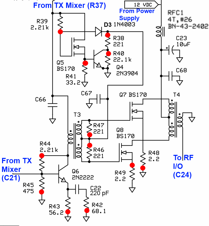
(above schematic has clickable areas that can be used for navigation)
(go directly to build notes)Driver/PA Bill of Materials
Stage Bill of Materials
(resistor images and color codes courtesy of WIlfried, DL5SWB's R-Color Code program)
| Check | Count | Component | Marking | Category |
|---|---|---|---|---|
| ❏ | 2 | 2.2 ohm 1/4W 5% | red-red-gld-gld
 | 1/4W |
| ❏ | 2 | 2.21 k 1/4W 1% | r-r-br-br-br
 | 1/4W |
| ❏ | 1 | 22.1 k 1/4W 1% | r-r-brn-r-br
 | 1/4W |
| ❏ | 3 | 221 1/4W 1% | red-red-brn-blk-brn
 | 1/4W |
| ❏ | 1 | 33.2 ohm 1% | ora-ora-red-gld-brn
 | 1/4W |
| ❏ | 1 | 475 1/4W 1% | y-v-grn-bl-br
 | 1/4W |
| ❏ | 1 | 56.2 1/4W 1% | grn-blu-red-gld-brn
 | 1/4W |
| ❏ | 1 | 1N4003 | 1N4003
 | Axial |
| ❏ | 1 | BN-43-2402 (no markings!) | none
 | Binocular core |
| ❏ | 1 | 4T #26 on BN-43-2402 (6") |
 | Choke |
| ❏ | 1 | 10uF/16 VDC |
 | Electrolytic |
| ❏ | 1 | #4 nylon washer | HDW | |
| ❏ | 1 | #6 screw, hex nut, starwasher | HDW | |
| ❏ | 1 | band-specific | misc | |
| ❏ | 7 | band-specific | misc | |
| ❏ | 1 | band-specific | misc | |
| ❏ | 1 | TO-220 heatsink Silpad |
 | Misc |
| ❏ | 1 | 2N2222 NPN transistor |
 | TO-18 |
| ❏ | 1 | heatsink for driver transistor |
 | TO-18 |
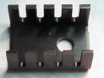
| ❏ | 1 | TO-220 heatsink for flat transistors |
 | TO-220 |
| ❏ | 1 | 2N3904 NPN Transistor | 2N3904
 | TO-92 |
| ❏ | 3 | BS170 N-Channel Enhancement Mode FET | BS170
 | TO-92 |
Band Specific Items for 160m Band
| Check | Designation | Component | Marking | Category | Orientation | Notes | Circuit |
|---|---|---|---|---|---|---|---|
| ❏ | C22 | omit for this band | Omit | Driver/PA | |||
| ❏ | C66 | 0.1 uF | (smt) black stripe
 | SMT 1206 | Driver/PA | ||
| ❏ | C67 | 0.1 uF | (smt) black stripe
 | SMT 1206 | Driver/PA | ||
| ❏ | C68 | 0.1 uF | (smt) black stripe
 | SMT 1206 | Driver/PA | ||
| ❏ | R42 | omit for this band | Omit | flat-horiz | Omit for 160 and 80,40m | Driver/PA | |
| ❏ | T3 | 6T/3T bifilar #30 on BN-43-2402 (12") |
 | Xfrmr | Driver/PA | ||
| ❏ | T3-core | BN-43-2402 (no markings!) | none
 | Binocular core | 43, NOT 61 | Driver/PA | |
| ❏ | T4 | 4T bifilar/5T #30 0n BN-43-2402 (12") |
 | Xfrmr | Driver/PA | ||
| ❏ | T4-core | BN-43-2402 (no markings!) | none
 | Binocular core | 43, NOT 61 | Driver/PA |
Band Specific Items for 80, 40m Band
| Check | Designation | Component | Marking | Category | Orientation | Notes | Circuit |
|---|---|---|---|---|---|---|---|
| ❏ | C22 | omit for this band | Omit | Driver/PA | |||
| ❏ | C66 | 0.1 uF | (smt) black stripe
 | SMT 1206 | Driver/PA | ||
| ❏ | C67 | 0.1 uF | (smt) black stripe
 | SMT 1206 | Driver/PA | ||
| ❏ | C68 | 0.1 uF | (smt) black stripe
 | SMT 1206 | Driver/PA | ||
| ❏ | R42 | omit for this band | Omit | flat-horiz | Omit for 160 and 80,40m | Driver/PA | |
| ❏ | T3 | 6T/3T bifilar #30 on BN-43-2402 (12") |
 | Xfrmr | Driver/PA | ||
| ❏ | T3-core | BN-43-2402 (no markings!) | none
 | Binocular core | 43, NOT 61 | Driver/PA | |
| ❏ | T4 | 4T bifilar/5T #30 0n BN-43-2402 (12") |
 | Xfrmr | Driver/PA | ||
| ❏ | T4-core | BN-43-2402 (no markings!) | none
 | Binocular core | 43, NOT 61 | Driver/PA |
Band Specific Items for 40, 30, 20m Band
| Check | Designation | Component | Marking | Category | Orientation | Notes | Circuit |
|---|---|---|---|---|---|---|---|
| ❏ | C22 | omit for this band | Omit | Driver/PA | |||
| ❏ | C66 | 0.1 uF | (smt) black stripe
 | SMT 1206 | Driver/PA | ||
| ❏ | C67 | 0.1 uF | (smt) black stripe
 | SMT 1206 | Driver/PA | ||
| ❏ | C68 | 0.1 uF | (smt) black stripe
 | SMT 1206 | Driver/PA | ||
| ❏ | R42 | omit for this band | Omit | flat-horiz | Omit for 160 and 80,40m | Driver/PA | |
| ❏ | T3 | 6T/3T bifilar #30 on BN-61-2402 (12") |
 | Xfrmr | Driver/PA | ||
| ❏ | T3-core | BN-61-2402 (no Markings!) | none
 | Binocular core | Driver/PA | ||
| ❏ | T4 | 3T bifilar/5T #30 0n BN-61-2402 (12") |
 | Xfrmr | Driver/PA | ||
| ❏ | T4-core | BN-61-2402 (no Markings!) | none
 | Binocular core | Driver/PA |
Band Specific Items for 30, 20, 17m Band
| Check | Designation | Component | Marking | Category | Orientation | Notes | Circuit |
|---|---|---|---|---|---|---|---|
| ❏ | C22 | 220 pF 5% | 221
 | Ceramic | Driver/PA | ||
| ❏ | C66 | 0.1 uF | (smt) black stripe
 | SMT 1206 | Driver/PA | ||
| ❏ | C67 | 0.1 uF | (smt) black stripe
 | SMT 1206 | Driver/PA | ||
| ❏ | C68 | 0.1 uF | (smt) black stripe
 | SMT 1206 | Driver/PA | ||
| ❏ | R42 | 68.1 1/4W 1% | blu-gry-brn-gld-brn
 | 1/4W | flat-horiz | Omit for 160 and 80,40m | Driver/PA |
| ❏ | T3 | 6T/3T bifilar #30 on BN-61-2402 (12") |
 | Xfrmr | Driver/PA | ||
| ❏ | T3-core | BN-61-2402 (no Markings!) | none
 | Binocular core | 61, NOT 43 | Driver/PA | |
| ❏ | T4 | 3T bifilar/5T #30 0n BN-61-2402 (12") |
 | Xfrmr | Driver/PA | ||
| ❏ | T4-core | BN-61-2402 (no Markings!) | none
 | Binocular core | 61, NOT 43 | Driver/PA |
Band Specific Items for 15, 12, 10m Band
| Check | Designation | Component | Marking | Category | Orientation | Notes | Circuit |
|---|---|---|---|---|---|---|---|
| ❏ | C22 | 220 pF 5% | 221
 | Ceramic | Driver/PA | ||
| ❏ | C66 | 0.01 uF | (smt)
 | SMT 1206 | Driver/PA | ||
| ❏ | C67 | 0.01 uF | (smt)
 | SMT 1206 | Driver/PA | ||
| ❏ | C68 | 0.01 uF | (smt)
 | SMT 1206 | Driver/PA | ||
| ❏ | R42 | 68.1 1/4W 1% | blu-gry-brn-gld-brn
 | 1/4W | flat-horiz | Omit for 160 and 80,40m | Driver/PA |
| ❏ | T3 | 5T/3T bifilar #30 on BN-61-2402 (12") |
 | Xfrmr | Driver/PA | ||
| ❏ | T3-core | BN-61-2402 (no Markings!) | none
 | Binocular core | 61, NOT 43 | Driver/PA | |
| ❏ | T4 | 3T bifilar/5T #30 0n BN-61-2402 (12") |
 | Xfrmr | Driver/PA | ||
| ❏ | T4-core | BN-61-2402 (no Markings!) | none
 | Binocular core | 61, NOT 43 | Driver/PA |
Driver/PA Summary Build Notes
- Install Bottomside Components
- Wind and Install Choke RFC1
- Wind and Install Transformers T3 and T4
- Test T3 and T4 Continuity
- Install the FET Stack
- Install the 2N2222A Transistor
- Install Remaining Topside Components
- Test the Stage
Driver/PA Detailed Build Notes
Top of the Board
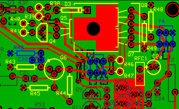
Wind and Install Choke RFC1
Take care to distinguish the correct binocular core - there are two types in this kit: BN-43-2402 and BN-61-2402; They are bagged and marked separately. This step (RFC choke) uses the BN-43-2402
See WB5RVZ Inductor Construction Hints for hints on winding and installing inductors.
RFC1 needs 4 turns (6") of #26 wire on a BN-43-2402 bino core.
- Before winding, take a small drill bit and twirl it in the core holes to smooth/remove any burrs that might otherwise short the coil. Better yet, if you have access to a mounted stone from a Dremel type tool (just held in your fingers - not powered), use that to smooth the rough edges (TX to iain MW0XEN for the tip).
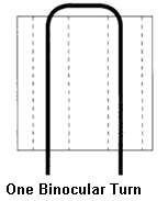
- Remember, when winding a binocular core like the BN-43-2402, each pass where the wire ends up at the same side where it started the pass counts as a turn.
- Use fine grit emery cloth to remove the enamel from the magnet wire up to within 1/8 inch of the core
- Solder the leads of RFC1
- Once soldered, verify continuity by applying 12V power to the board and measuring the voltage at the via for the positive lead of C23. If you see the 12V rail value, then RFC1 was likely soldered correctly.
- Remove power from the board
| Check | Designation | Component | Marking | Category | Orientation | Notes |
|---|---|---|---|---|---|---|
| ❏ | RFC1 | 4T #26 on BN-43-2402 (6") |
 | Choke |
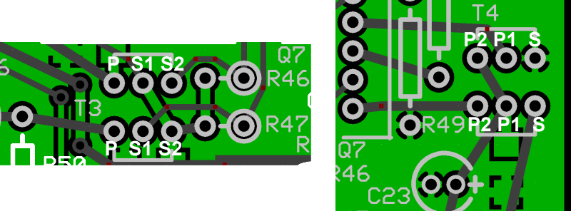
Wind and Install Transformers T3 and T4
See WB5RVZ Inductor Construction Hints for hints on winding and installing inductors.
Several builders have had problems fitting those windings in on T3 and T4. The secret is, as Charles, W4CEW, put it, "A tooth pick and careful winding. Ues the tooth pick to compress the wire in the opening just enough to get the wire through. I tin and solder the ends together so the bifiliar winding wont seperate and wad up."
If you are unfamiliar with winding and installing inductors, you may want to refer to the WB5RVZ construction hints for coils (toroidal) and transformers ( toroidal and binocular). Click here for details on identifying toroid cores.
Decoding the trqansformer specifications:
Transformers' windings are specified using the pattern "nnT/wXmmT" or "wXmmT/nnT", where:
- "nn" is the number of turns in the single winding
- "mm" is the number of turns in the multiple windings
- "w" = the number of multiple windings (e.g., 2 = bifilar; 3 = trifilar, etc.)
Thus, e.g., "18T/2x9T bifilar #30" means, using #30 wire, produce a single 18 turn primary winding and two 9-turn secondary windings; "2x9T bifilar/ 18T #30" means, using #30 wire, produce two 9-turn primary windings and a single 18 turn secondary winding.
| Check | Designation | Component | Marking | Category | Orientation | Notes | ||||||||||||||||||
|---|---|---|---|---|---|---|---|---|---|---|---|---|---|---|---|---|---|---|---|---|---|---|---|---|
| ❏ | T3 | band-specific |
| misc | ||||||||||||||||||||
| ❏ | T3-core | band-specific | misc | |||||||||||||||||||||
| ❏ | T4 | band-specific |
| misc | ||||||||||||||||||||
| ❏ | T4-core | band-specific | misc |
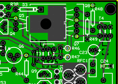
Test T3 and T4 Continuity
Test the continuity of T3 and T4 primaries and secondaries using the points shown in the graphic below:
| Point Pair | Expected Ohms | Measured |
|---|---|---|
| A-to-A | 0 | __________ |
| B-to-B | 0 | __________ |
| C-to-C | 0 | __________ |
| D-to-D | 0 | __________ |
Install the FET Stack
Matching BS170s
There has been considerable discussion on the reflector concerning the problems resulting from mismatched BS170s in Q7 and Q8. While not absolutely necessary, it may still be advisable to use the circuit from Alan, G4ZFQ, to match up 3 of BS170s to serve as Q5, Q7 and Q8. Alan has an excellent article discussing this issue in detail (and provides the circuit for measuring/matching the BS170s..
.Installation
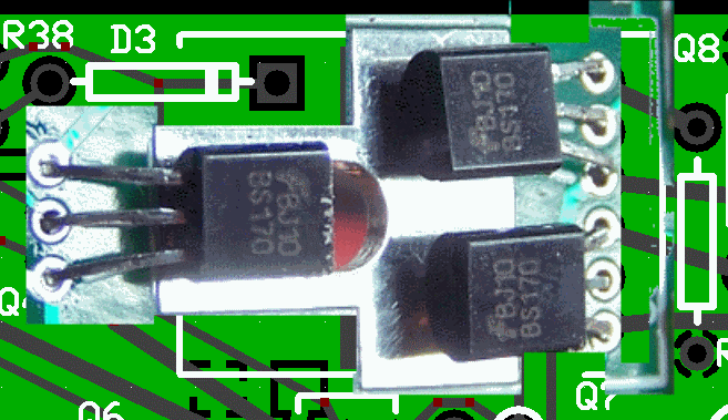
Installing the three FET transistors and their heatsinking components is performed in the same fashion as it was in the RXTX V6.3 (FET Transistor/Heatsink Stack). See the instructions for the RXTX PAF Stage.
Transistors Q5, Q7, and Q8 are mounted with their flat side facing upward so that the entire flat side of each transistor will be under an aluminum TO220 heat sink.
- Bend the leads of Q5, Q7, and Q8 at right angles away from the flat side of each transistor at a distance from the plastic body of each transistor so that its case end is very close to the heat sink mounting hole in the board.
- When a transistor is properly placed solder one of its leads from the top side of the board to tack the transistor in position.
- Remember, just tack 1 lead of each FET
- After Q5, Q7, and Q8 are tacked in place with their flat sides facing upward, mount the heat sink with the Sil-Pad between the flat sides of the transistors and the bottom surface of the heat sink. The heat sink stack up should be as follows: from the bottom of the circuit board:
- the ˝ inch long 6-32 Phillips machine screw,
- the circuit board,
- the transistors with flat faces upward,
- the TO220 Sil-Pad,
- the TO220 heat sink with fins upward,
- the #6 star washer,
- and the 6-32 hex nut.
- Tighten the 6-32 hardware carefully to firmly compress the stack while holding the heat sink in alignment with the rectangular markings on the circuit board. Be careful that the tightening of the #6 hardware does not cause a twisting motion of the transistors.
- When the transistors are firmly clamped between the board and heat sink with good alignment, complete the soldering of the transistor leads and trim the lead flush to the bottom of the board.
| Check | Designation | Component | Marking | Category | Orientation | Notes |
|---|---|---|---|---|---|---|
| ❏ | R49 | 2.2 ohm 1/4W 5% | red-red-gld-gld
 | 1/4W | flat-vert | |
| ❏ | R48 | 2.2 ohm 1/4W 5% | red-red-gld-gld
 | 1/4W | flat-vert | |
| ❏ | D3 | 1N4003 | 1N4003
 | Axial | horiz - cathode (band) to right | |
| ❏ | Q05 | BS170 N-Channel Enhancement Mode FET | BS170
 | TO-92 | Take ESD precautions | |
| ❏ | Q07 | BS170 N-Channel Enhancement Mode FET | BS170
 | TO-92 | Take ESD precautions | |
| ❏ | Q08 | BS170 N-Channel Enhancement Mode FET | BS170
 | TO-92 | Take ESD precautions | |
| ❏ | PA-sil | TO-220 heatsink Silpad |
 | Misc | ||
| ❏ | PA-hs | TO-220 heatsink for flat transistors |
 | TO-220 | ||
| ❏ | hdw-hs | #6 screw, hex nut, starwasher | HDW | Used to mount TO-220heatsink | ||
| ❏ | R44 | 2.21 k 1/4W 1% | r-r-br-br-br
 | 1/4W | flat-vert | |
| ❏ | R46 | 221 1/4W 1% | red-red-brn-blk-brn
 | 1/4W | E-W | |
| ❏ | R47 | 221 1/4W 1% | red-red-brn-blk-brn
 | 1/4W | E-W |
Install the 2N2222A Transistor
Install Surrounding Components
Before actually installing the 2N2222A transistor, you need to install the surrounding components (which will fall under the "shadow" of the transistor's heatsink once it is installed.
Install Transistor and Heatsink
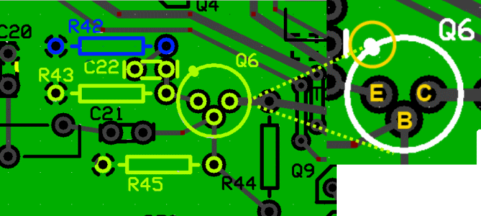
Installation of the 2N2222 driver transistor is done similarly to the 2N2222 in the RXTX V6.3 kit.
- Prepare the heat sink for installation by placing the heat sink on a flat surface, flat-side down. Align the small tab on the transistor case with the slit in the side of the heat sink.
- Press the TO-18 heat sink onto Q6 by pressing uniformly on the lower rim of the transistor to fully insert it into the heat sink.
- A #4 nylon washer is included in the kit as a spacer between the bottom of the transistor and the circuit board. Be sure to use the nylon washer in mounting this transistor. This is necessary in order to keep the metal case off of the board and avoid shorts between the leads of the transistor.
- Slip the leads of the transistor through the nylon washer’s hole
- Snug the transistor to the circuit board.
- Exercise care to make sure the emitter lead of Q6 (by the metal tab on the transistor case) goes to the hole closest to the corresponding silkscreen emitter mark on the circuit board.
- Solder the three leads
| Check | Designation | Component | Marking | Category | Orientation | Notes | ||||||||||||||||||
|---|---|---|---|---|---|---|---|---|---|---|---|---|---|---|---|---|---|---|---|---|---|---|---|---|
| ❏ | R43 | 56.2 1/4W 1% | grn-blu-red-gld-brn
 | 1/4W | flat-horiz | |||||||||||||||||||
| ❏ | R45 | 475 1/4W 1% | y-v-grn-bl-br
 | 1/4W | flat-horiz | |||||||||||||||||||
| ❏ | R42 | band-specific |
| misc | flat-horiz | Omit for 160 and 80,40m | ||||||||||||||||||
| ❏ | C22 | band-specific |
| misc | ||||||||||||||||||||
| ❏ | Q06 | 2N2222 NPN transistor |
 | TO-18 | ||||||||||||||||||||
| ❏ | Q06-hs | heatsink for driver transistor |
 | TO-18 | ||||||||||||||||||||
| ❏ | hs_wshr | #4 nylon washer | HDW | slipped over leads of 2N2222 |
Install Remaining Topside Components
Be careful with the resistors. There are resistors (221, 2.21k, 21.1k) whose color codes are extremely easy to get mixed up. Even Leonardo DaVinci would have used an ohmmeter on these had he had one! Those reds and browns are really close.
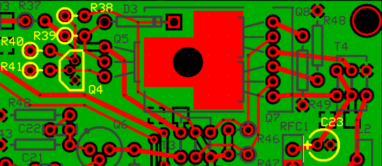
| Check | Designation | Component | Marking | Category | Orientation | Notes |
|---|---|---|---|---|---|---|
| ❏ | Q04 | 2N3904 NPN Transistor | 2N3904
 | TO-92 | ||
| ❏ | R41 | 33.2 ohm 1% | ora-ora-red-gld-brn
 | 1/4W | W-E | |
| ❏ | R40 | 22.1 k 1/4W 1% | r-r-brn-r-br
 | 1/4W | W-E | |
| ❏ | R39 | 2.21 k 1/4W 1% | r-r-br-br-br
 | 1/4W | W-E | |
| ❏ | R38 | 221 1/4W 1% | red-red-brn-blk-brn
 | 1/4W | W-E | |
| ❏ | C23 | 10uF/16 VDC |
 | Electrolytic |
Bottom of the Board
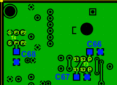
Install Bottomside Components
| Check | Designation | Component | Marking | Category | Orientation | Notes | ||||||||||||||||||
|---|---|---|---|---|---|---|---|---|---|---|---|---|---|---|---|---|---|---|---|---|---|---|---|---|
| ❏ | C66 | band-specific |
| misc | ||||||||||||||||||||
| ❏ | C67 | band-specific |
| misc | ||||||||||||||||||||
| ❏ | C68 | band-specific |
| misc |
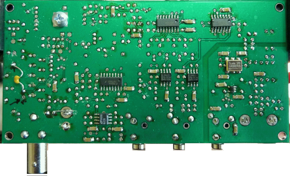
Driver/PA Completed Stage
Top of the Board
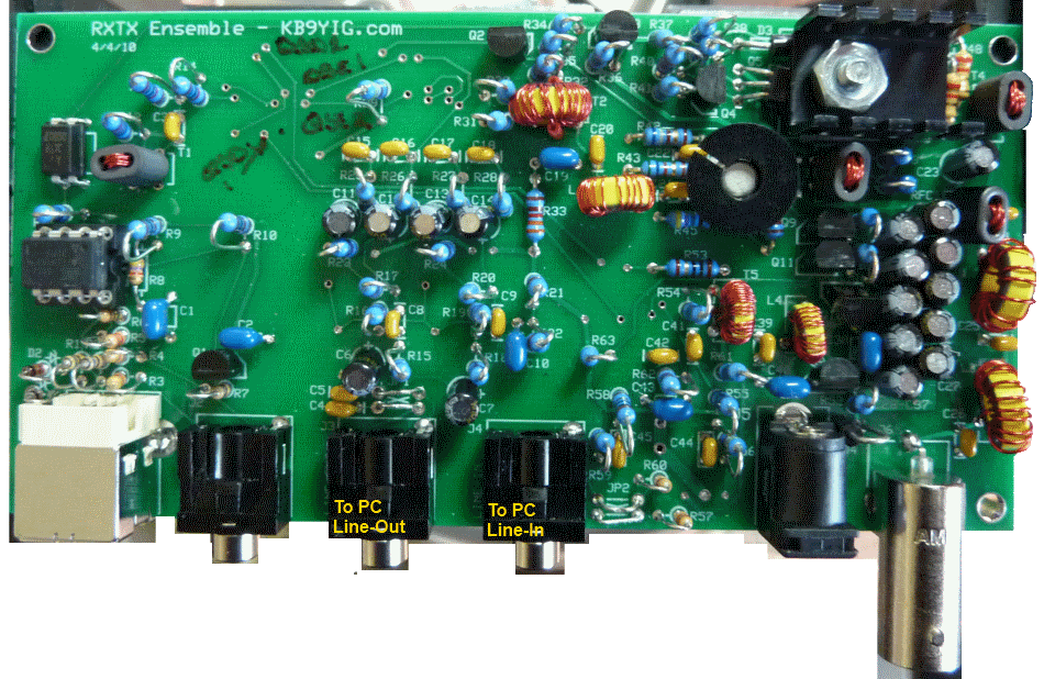
Bottom of the Board
Driver/PA Testing
Current Draw
Test Setup
Connect the USB cable and power up the board, measuring the RX current draw.
Then activate PTT and measure the current draw again.
To activate PTT, use clip leads to connect pins 3 and 4 of U4.
Test Measurements
| Testpoint | Units | Nominal Value | Author's | Yours |
|---|---|---|---|---|
| PTT NOT activated | mA | < 35 | 25.2 | _______ |
| PTT activated | mA | < 150 | 126.7 | _______ |
PA Standing Current and Forward Bias
Test Setup
Connect the USB cable, and Power. Activate PTT.
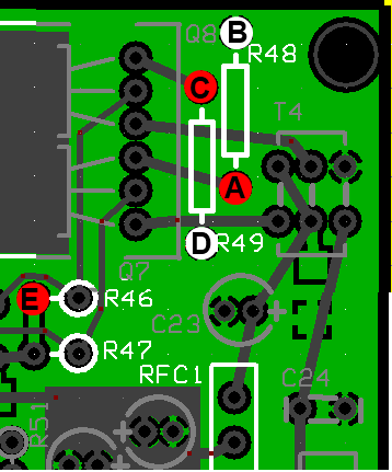
Measure PA standing current by activating PTT and measuring the voltages across resistors R48 and R49. The DC voltage across each resistor should be 55 mVDC. +/- 10mVDC. If the voltages are different from each other, the difference should not be more +/- 10% of the average of the two voltages.
Note: If your measurements across R48 and R49 are way off of spec, please review Alan, G4FZQ's Excellent article on matching the BS170s in the PA stage. It contains some valueable information about the potential for mismatched BS170 transistors and approaches to solution of this problem.
Then check the forward bias voltage at the junction of R46 and R47.
Check the voltage at the R35 hairpin. With PTT active you should get the "S12V" value approximately equal to the 12 V rail. With PTT InActivated that same testpoint should yield near 0 volts
Test Measurements
| Testpoint | Units | Nominal Value | Author's | Yours |
|---|---|---|---|---|
| Voltage between Testpoints "A" and "B" (across R48) | mV dc | 55 | 54.3 | _______ |
| Voltage between Testpoints "C" and "D" (across R49) | mV dc | 55 | 54.4 | _______ |
| Voltage (WRT regular ground) at Test Point "E" | V dc | 2.2 | 2.68 | _______ |
| Voltage (WRT regular ground) at R35 hairpin (PTT Active) | V dc | 12 | tbd | _______ |
| Voltage (WRT regular ground) at R35 hairpin (PTT InActive) | V dc | 0 | tbd | _______ |
RF Output
Test Setup
A quadrature audio source can be used for initial testing of the transmit function. Quadrature audio can be provided from a PC soundcard line-out if a program such as IQ GEN by DL6IAK or Rocky is installed on the PC.
Rocky can also be used.
This tests requires Rocky to be set up for transmit. If you are using Rocky on Vista or Windows 7, as opposed to Windows XP, you will need two expernal, USG soundcards. The author uses a Soundblaster Live 24 USB soundcard for the RX and TX I and Q signals and a cheap in-line usb "dongle-type" soundcard for Mic input and speaker/phone output.
If you have Windows XP, then you will still need an extrnal sound card for the I and Q for RX and TX, but you can use the on-board card for the mike and speaker in/outputs.
- Use the same Rocky setup from the RX Opamps Stage Testing section
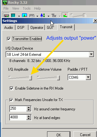
- Set up Rocky to transmit (i.e., send out I and Q signals) .
-
- Connect the soundcard's Line Out corresponding jack (J3) on the Ensemble RXTX board.
- Connect your antenna jack (J6) to a 50 ohm load
- for illustration we are using the
Norcal Dummy Load
Note: An on-board Schottky diode and capacitor on this dummy load provides an rf detector across the dummy load's terminals that rectifies the RF voltage and provides a peak detected DC output which can be measured using the dc settings on your DMM.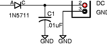 .
. - Power up the RXTX with PTTactivated
- During testing, take care not to leave the Softrock at PTT=high for any length of time - the heat sink and the PA FETs will get uncomfortable hot if you do!
- Set the center frequency of Rocky accordingly and, using your mouse, select a frequency on the spectrun display approximetaly 15 kHz above the center frequency (e.g., 14.065 MHz when the center frequency is set for 14.050 MHz).
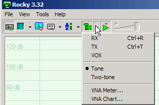
- Click on the "TX" button at the top of the screen, select "Tone" to get a single sine wave out of the PC's sound card (I and Q) outputs.
-
- Check for DC voltage at the 50 ohm dummy load's DC output as Rocky's IQ Amplitude audio level slider is increased towards max
-
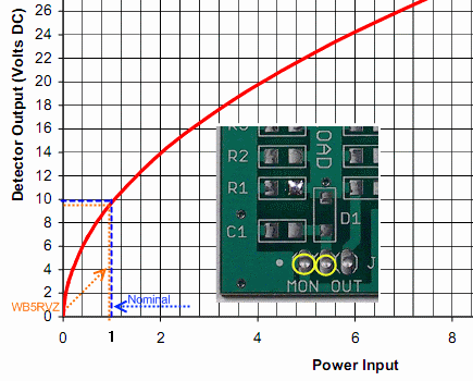
The DC voltage at the 50 ohm load should go to ~10 Vdc, (1 watt output). - If the output power is about 1/2 what it should be, you should check the Winding and installation of T3 or T4.
- If the output is much over 10V (as the author experienced) you need to back off of the amplitude in Rocky's "transmit" tab until the voltage approximates 10.
Test Measurements
| Testpoint | Units | Nominal Value | Author's | Yours |
|---|---|---|---|---|
| Rectified DC Output at dummy load | V dc | ~10 | 12.2 (a little too hot!) | _______ |
PA Output Reception Test
Test Setup
In the test setup above, tune an external radio to the TX output frequency (approximetaly 15 kHz above the Softrock's center frequency, e.g.,, 14.065 MHz when the center frequency is tuned to 14.050 MHz.). Loosely couple the receiver to the dummy load.
You should see/hear the signal on the receiver.
PA Output - Scope Test
Test Setup
(Usual caveats as to author's scope's accuracy and stability apply here)
- Use the same Rocky setup from above with the board powered up and PTT activated
- Click on Rocky's "TX" button and transmit a tone
- check for RF output across the 50 ohm load as Rocky's IQ Amplitude audio level is increased towards max
- The RF voltage across the 50 ohm load should go to ~20V p-p, (1 watt output), when the quadrature audio inputs
are each at 2.4V p-p..
- The RF output waveform across the 50 ohm load should appear as a clean looking sine wave when viewed with a scope. The frequency of the RF voltage should be equal to the center frequency + or - 15 kHz where the + or - frequency offset depends on the line-out signal phase relationship between the two line-out channels.
- The example shown below has the correct wave form and frequency, but the V p-p and frequency are approximate (however this may well be due to the calibration and accuracy of the author's cheapo scope).
- The power output is derived using the following formula:
[ (Vpk)2 * 0.125 ] / 50
= [ (21.5)2 * 0.125 ] / 50
= 1.16 W (1156 mW)
Test Measurements
| Testpoint | Units | Nominal Value | Author's | Yours |
|---|---|---|---|---|
| RF Voltage (across 50 ohm dummy load) | V p-p | ~20 | 29.1 (a little too hot!) | _______ |
TX I/Q Balancing
Test Setup
Before going on the air and after balancing the RX I and Q signals, the builder must balance the Transmit I and Q signals to remove the images on transmit and avoid the embarrassment of inadvertently causing QRM at the image frequency. Click here to view the page on this procedure (from the RXTX V6.3 builders' notes).
Please note that the TX I/Q balancing must be done for each frequency range in which you will operate. Rocky will save the settings (except for the slider values); however, these may change over time. There is a very helpful discussion of this topic on the Yahoo Softrock40 reflector at message #45816.


