Introduction
The first stage covers a lot of initialization work, in addition to installing and testing the three dc power supplies - 12, 5, and 3.3 Vdc. (Note: throughout these notes we will refer to "12V". In fact, the kit is ideally powered by a 13.8V supply - we'll use a nominal 12V.
The first step is to install ALL of the SMT capacitors (they are numbered C40 and above) to the bottom of the board. This helps protect the ICs from static discharge failures later in the build. It also gently introduces the builder to working with SMT components. A test after the SMT caps are mounted is to make sure there are no shorts to ground on the +5 and +3.3 volt power nets.
Schematic
Summary Build Notes
- Fasten Board Mounting Hardware
- Install All SMT Caps (some are .1, some are .o1 uF - see bottomside map below) and test for shorts
- Install U5
- Install U4 and D1
- Install electrolytic caps and ceramic caps
- Install ground testpoint loop
- Test the stage
Bill of Materials
Power Supplies
| Check | Designation | Component | (Color) Code | Type | Qty | Notes |
|---|---|---|---|---|---|---|
| [__] | C17 | 10 uF 16V | electrolytic | 1 | S=+ | |
| [__] | C18 | 10 uF 16V | electrolytic | 1 | S=+ | |
| [__] | C19 | 10 uF 16V | electrolytic | 1 | S=+ | |
| [__] | C20 | 10 uF 16V | electrolytic | 1 | S=+ | |
| [__] | C21 | 10 uF 16V | electrolytic | 1 | S=+ | |
| [__] | C22 | 10 uF 16V | electrolytic | 1 | S=+ | |
| [__] | C23 | 10 uF 16V | electrolytic | 1 | S=+ | |
| [__] | C24 | 10 uF 16V | electrolytic | 1 | S=+ | |
| [__] | C25 | 10 uF 16V | electrolytic | 1 | S=+ | |
| [__] | C26 | 10 uF 16V | electrolytic | 1 | S=+ | |
| [__] | C32 | 4.7 uF | 475 | ceramic | 1 | |
| [__] | C33 | 4.7 uF | 475 | ceramic | 1 | |
| [__] | D1 | 1N4003 | Diode | 1 | ||
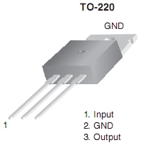
| [__] | U4 | LM7805 | IC TO-220 5V voltage regulator | 1 | (top) | |
| [__] | U5 | LP2992AIM5-3.3V | SOT-23 3.3v Regulator | 1 | (bottom - code="LFEA") |
SMT Caps
Note that there are two different types of SMT cap: 0.1 uF and 0.01 uF
| Check | Designation | Component | (Color) Code | Type | Qty | Notes |
|---|---|---|---|---|---|---|
| Check | Designation | Component | (Color) Code | Type | Qty | Notes |
| [__] | C52 | 0.01uF | SMT 1206 CAP | 1 | ||
| [__] | C53 | 0.01uF | SMT 1206 CAP | 1 | ||
| [__] | C54 | 0.01uF | SMT 1206 CAP | 1 | ||
| [__] | C56 | 0.01uF | SMT 1206 CAP | 1 | ||
| [__] | C57 | 0.01uF | SMT 1206 CAP | 1 | ||
| [__] | C58 | 0.01uF | SMT 1206 CAP | 1 | ||
| [__] | C59 | 0.01uF | SMT 1206 CAP | 1 | ||
| [__] | C61 | 0.01uF | SMT 1206 CAP | 1 | ||
| [__] | C40 | 0.1uF | SMT 1206 CAP (black marked strip) | 1 | ||
| [__] | C41 | 0.1uF | SMT 1206 CAP (black marked strip) | 1 | ||
| [__] | C42 | 0.1uF | SMT 1206 CAP (black marked strip) | 1 | ||
| [__] | C43 | 0.1uF | SMT 1206 CAP (black marked strip) | 1 | ||
| [__] | C44 | 0.1uF | SMT 1206 CAP (black marked strip) | 1 | ||
| [__] | C45 | 0.1uF | SMT 1206 CAP (black marked strip) | 1 | ||
| [__] | C46 | 0.1uF | SMT 1206 CAP (black marked strip) | 1 | ||
| [__] | C47 | 0.1uF | SMT 1206 CAP (black marked strip) | 1 | ||
| [__] | C48 | 0.1uF | SMT 1206 CAP (black marked strip) | 1 | ||
| [__] | C49 | 0.1uF | SMT 1206 CAP (black marked strip) | 1 | ||
| [__] | C50 | 0.1uF | SMT 1206 CAP (black marked strip) | 1 | ||
| [__] | C51 | 0.1uF | SMT 1206 CAP (black marked strip) | 1 | ||
| [__] | C55 | 0.1uF | SMT 1206 CAP (black marked strip) | 1 | ||
| [__] | C60 | 0.1uF | SMT 1206 CAP (black marked strip) | 1 | ||
| [__] | C62 | 0.1uF | SMT 1206 CAP (black marked strip) | 1 | ||
| [__] | C63 | 0.1uF | SMT 1206 CAP (black marked strip) | 1 | ||
| [__] | C64 | 0.1uF | SMT 1206 CAP (black marked strip) | 1 | ||
| [__] | C65 | 0.1uF | SMT 1206 CAP (black marked strip) | 1 |
Detailed Build Notes
Board Hardware
- a 3/8 inch long 4-40 Phillips machine screw,
- a 1/8 in long nylon spacer,
- the circuit board,
- a #4 nylon washer and
- a 4-40 hex nut.
Install SMT Caps
First, mount all of the SMT caps for the bottom of the main board. The 8 0.01 uF caps are found in a clear plastic strip. The 18 0.1 uF caps are in a plastic strip marked with a black stripe. (There are actually 20 caps in the kit; you have two free throws!)
Use the graphic below to determine placement. The 0.01 uF caps' locations are marked in the picture with yellow solder pads; the 0.1 uF caps are marked with white solder pads.
- Mount the eight 0.01 uF caps (from the clear plastic strip) first. Use the yellow colored pads.
- Then mount the eighteen 0.1 uF caps (from the black-marked plastic strip) on the remaining (whte) SMT cap pads
Gotcha: (this applies, as well, to all soldering work on the bottom of the board) be careful when soldering SMT components to avoid "splashover" of molten solder into/onto adjacent holes. It is very easy to plug up a hole and be forced at some later stage to stop work and "unplug" the hole. A fine toothpick is a handy solder "guard" when you need to protect one or more adjacent holes.
Test SMT Caps for shorts
- Perform this test BEFORE moving on to the Power Supply components. Note: an auto-ranging ohmmeter will likely indicate a brief reading of several tens of MegOhms before finally going to off-scale.
- Note: the test points for the 5 and 3.3 Vdc rails are at JP1. JP1 is for selecting either 3.3 volts or 5 volts to the second set of holes under the 4-position DIP switch.
- JP1 is not needed for normal operation of the v6.3 board.
- refer to the 12, 5, and 3.3 V test points. referenced in the testing section below
- using your ohmmeter, test the "power in" terminals for any short
- next, test the +12 V rail for any shorts to ground
- next, test the 5 volt rail for any short to ground
- finally, test the 3.3v rail for any short to ground.
- If a short is discovered on any line, check back through the main schematic to identify potential SMT caps (C40-C65) which could be shorted. Resolder the offender.
Install U5 (LP2292AIM5-3.3v)
- Install U5 (LP2292AIM5-3.3v) on the bottom side of the board (vicinity of C52-C53).
- Install this 3.3 V voltage regulator first.
- Take care with this IC. It is very tiny and installation is very prone to solder bridges. (see the SMT IC Installation Guidelines). Be very careful not to launch this chip with your tweezers. You'd likely never find it again!
- Take ESD precautions when working with this IC.
| Check | Designation | Component | Type | Qty | Notes | Orientation |
|---|---|---|---|---|---|---|
| U5 | SOT23-5 LP2992AIMS-3.3V | 3.3v Regulator | (bottom - code="LFEA") | 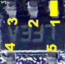
|
Install Power Supply Topside Components
Install U4 (LM7805)
- Install the 5 volt regulator. It mounts on top of the circuit board and the tab is fastened
to the circuit board by 4-40 hardware (4-40 machine screw, #4 star lock washer,
and hex nut) provided in the kit.
Watch out for the potential for the lower edge of this IC to overlap the +12 V test point and the C32 mounting holes.
- Bolt U4 to the board and solder and clip the leads.
Install D1 (1N4003)
Install D1 "flat" style, with the anode end in the round hole and the cathode end in the square hole

Install Electrolytics - C17-C26
Pay careful attention to the polarity of the electrolytic capacitors (C17-C26). The positive lead is the longer lead; the negative lead is the lead marked by a grey stripe down the side of the can. The positive lead is oriented toward the "south" of the board.
Install ceramic Capacitors
Install a loop for ground testpoints.
- Install a short piece of hookup wire (the long lead snipped from D1 after its installation is great for this purpose) into the hole near the center of the board at the bottom edge designated "GND" to allow a ground test point.
- Note, use a fairly stout piece of wire because this will get a lot of abuse during testing.
Completed board
Topside
Bottomside
Testing
Current Draw (DMM)
- Before you power the board up for the first time, connect a ma meter in series with the power lead and to be safe, put a 1k ohm resistor in series with the power lead. This can be in either the + or - line. This will limit the current flow to <=12 mA if you have a short on the board.
- After you see that the current isn't excessive, remove it, and re-measure the current draw. Subsequent tests in this stage are with the current-limiting resistor OUT of the circuit.
- The current draw with this initial stage and no other loads should be < 4 mA
- The author measured 3.1 mA.
- Your measurement is:______________________________
12 Volt Rail
- Power up the board with 12 Vdc
- Using a DMM, measure the voltage with respect to ground at the +12 V point on the board.
- This should be approximately 12 volts DC. It should show a voltage drop from the power source on the order of .5 to .7 Vdc, representing the effect of D1's ohmic resistance in the circuit.
- The author's board measured 11.4 Vdc with a power source that measured ~12 Vdc).
- Here is a simulation of the expected rail voltage, showing D1's effect:
-
- Your power source measurement is ________________________
- Your 12 V testpoint measurement is ________________________
5 Volt Rail (DMM - 5 Vdc)
- Power up the board with 12 Vdc
- Using a DMM, measure the voltage with respect to ground at the +5V point of JP1 (just above U6 on the top of the board).
- This should be in the range of 4.5 - 5.5 volts DC.
- The author's board measured 4.97Vdc).
- Your measurement is_______________________
3.3 Volt Rail (DMM - 3.3 Vdc)
- With the board powered up and using a DMM, measure the voltage with respect to ground at the 3.3V test point of JP1.
- This should be approximately 2.9 - 3.6 volts DC (the author's board provided 3.28 Vdc).
- Your measurement is___________________________
- If you do not get a good 3.3 Vdc reading, go back and check the soldering on U5.