Introduction
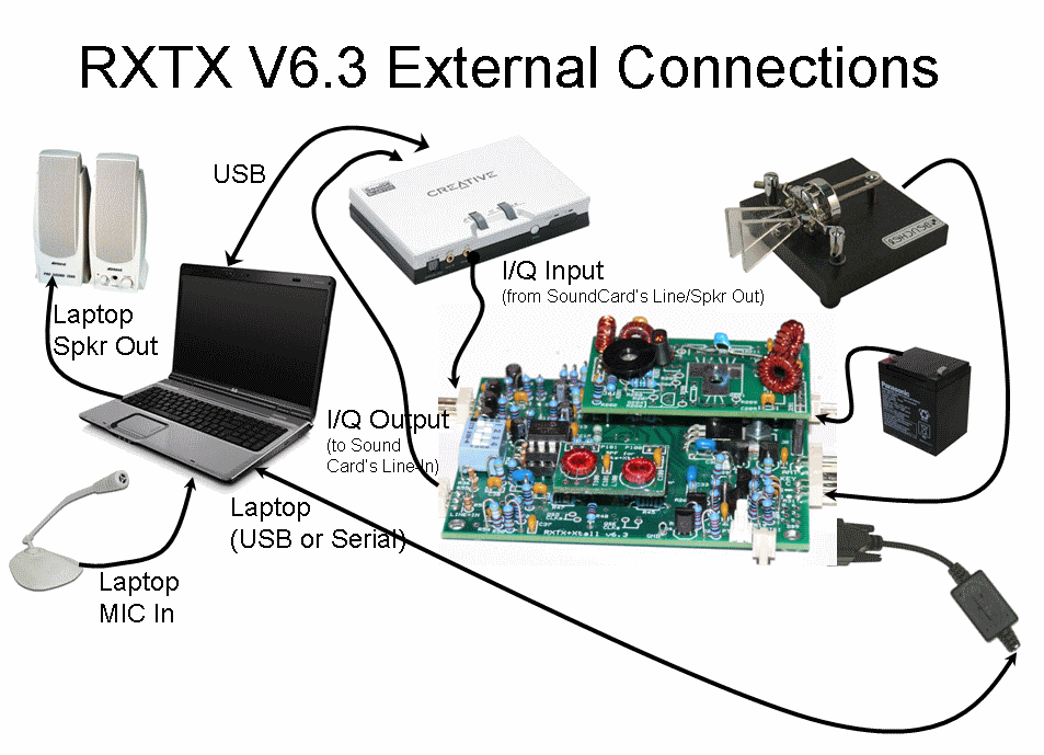
Once actual construction is completed you will want to connect the rig to the outside world. The possible connections (depending upon your use - here we assume you will be using Rocky for RX, TX, PTT, and keyer) are:
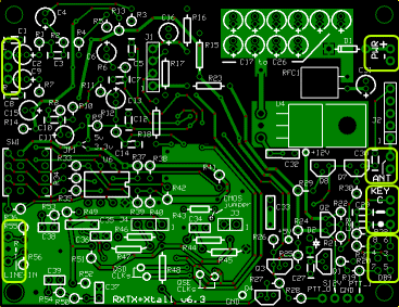
- Power (right-hand edge of the board, near the top)
- Antenna (ANT/RET - right hand edge, near half-way down)
- Keyer (right hand edge, just below antenna connection. Three terminals: C=common, .=dot, -=dash)
- Serial Connection (for PTT and/or keyer - right-hand edge of the board, at bottom)
- TX I and Q audio inouts (left-hand edge, near top - Ring, Tip, and ground)
- RX I and Q audio outputs (left-hand edge, near bottom - Ring and Tip)

Soundcards and SSB or CW Transmit Capability
Mark, KE1L, sums this all up as well as anyone:
To transmit and receive SSB you need a total of two sound inputs and two outputs. One input goes from the SoftRock to the computer for the received signal; the other is for the microphone. One output goes from the computer to the SoftRock for the transmitted signal; the other goes to the speaker or headphones.
Transmitting CW only requires one audio input (plus some way of interfacing the key or paddle if you use one) but you still need two outputs.
VAC (Virtual Audio Cable) doesn't help with this problem. In the context of SDR the main use of VAC is to be able to use sound cards that are otherwise not recognized by the SDR software. There are still two different signals that need to go into the computer and two different signals to come out; no clever management of a single sound card with just one input and one output can change that.
There are a variety of ways to get the necessary inputs and outputs, including two sound cards, sound cards with multiple I/O, a combination of a sound card and an internal sound interface, or a USB headset combined with some other form of I/O.
If you have two interfaces of varying quality you should use the best one for the (I and Q) signals to and from the SoftRock, and the lesser one for speakers and microphone.
Connection Locations

Summary Build Notes
- Install RX I/Q leads
- Install TX I/Q leads
- Install antenna leads
- Install Power leads
- Install keyer connection
- Install Rocky serial interface leads and socket
Detailed Build Notes
Audio (I/Q) Connection

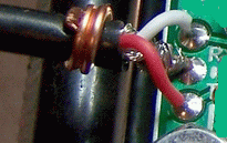
Sample audio cable connection
RX I and Q Audio output - LINE IN
These are the Ring(Q) and Tip audio outputs of the board, located at the bottom left edge of the board.
Depending upon your ultimate
enclosure/mounting requirements, you want to connect these three pads to good quality shielded
2 conductor audio cable, terminated either by a 3.5 mm mini plug or a mini jack.
Use a short length of solid hookup wire, soldered to the shielding and to the ground/common connection, and wrapped firmly around
the outer insulation of the cable as a strain relief mechanism.
If you plan on using the same sound card for both the RX and TX I and Q signals, you can reduce the possibility of ground loops (and the attendant noise in your RX) by NOT grounding the RX cable's shield and, instead, sharing the common ground in the TX cable. If you do this and you mount a stereo jack in your metal enclosure, you should be sure to use an isolated stereo jack for your RX output jack, such as the Markertek 30-711 jack
TX I and Q Audio input - "L - R"
These are the Left and Right audio outputs of the PC when in transmit mode. The connection points located at the top left edge of the board.
Depending upon your ultimate
enclosure/mounting requirements, you want to connect these three pads to good quality shielded
2 conductor audio cable, terminated either by a 3.5 mm mini plug or a mini jack.
Use a short length of solid hookup wire, soldered to the shielding and to the ground/common connection, and wrapped firmly around
the outer insulation of the cable as a strain relief mechanism.
If you plan on using the same sound card for both the RX and TX I and Q signals, you can reduce the possibility of ground loops by NOT grounding the RX cable's shield and, instead, sharing the common ground in the TX cable. If you do this and you mount a stereo jack in your metal enclosure, you should be sure to use an isolated stereo jack, such as the Markertek 30-711 jack
Experiment with various grounding/connection configurations to give the least disturbance around the center frequency. Get it right before boxing it up in an enclosure.
Antenna Connection

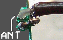
Sample Antenna Connection
ANT/RET
These are the ANT and Ground (unmarked) connections located on the right-hand side of the board, near the top.
Use RG-174U 50 ohm "micro" coax for the antenna connection, There is a good discussion of RG-174 coax and techniques for installing connectors available on the internet.
Use the strain-relief technique illustrated above.
Power Connection

Sample Power Connection
PWR
Use the conventional red/black wire for the power line +/- connections with the connector of your choice.
Keyer Connection

Keyer Connection Leads
KEY
This works for your keyer, providided you have also connected the serial connector from Rocky. Connect leads from your keyer's common, dot, and dash lines to the corresponding points just below the antenna connection.
If you plan to mount a stereo jack in your metal enclosure to connect the keyer plug, be sure to use an isolated jack in order to eliminate ground loops.Rocky Serial Interface Connection

DB9 Connector Location
DB9
This provides PTT signals from and, optionally, keyer dots and dashes to, Rocky through a standard DB9 connector. Plug the serial connector from your PC (directly or via a USB-to-Serial adaptor) into the DB9 connector wired into the holes at the bottom right edge of the board.
The SRv6.3 PTT_I can be activated with from +4.5 to +12 Vdc