Introduction
This is the final (no pun intended) stage of the build, where the output signal from the Mixer (QSE) stage is amplified and delivered to the antenna. When you have completed this stage, you are ready to set up the radio for actual tranceiving use.
This is the largest and most complicated stage in the entire build. Because of this, there are several intra-build test activities to complete during the build, mostly checking for correct installation of the inductors
There are some tricky maneuvers in this stage, including, but not limited to, the following gotchas (using the 80/40m PAF board as an example):
- Six inductors to wind and install (including the 34 (plus 2x17)turn T200 and the 33 turn L200-2)
- Two binocular inductors to wind and mount that have been the source of many problems
- Some careful bending of the leads of and mounting of Q201, Q202, and Q203
- Installing the heat sinks on the three transistor array and the Q200 (2N2222)
- installing some resistors (flat) that must be carefully placed so as not to interfere with the placement of Q200 and its heat sink
The build instructions for this main PAF stage use the BOM values for the 80/40m PAF, which the author built as part of this documentation. If you are building a PAF board for a different band(s), you should refer to the Bill of Materials for that other band(s) and substitute their values herein.
The other bands' BOMs are:
Schematic
(Click for full TX Schematic)
Summary Build Notes
- Install all SMT caps (all are 0.1 uF). Test for shorts
- Install flat components:R200, R201, R203, R210, R211; D200
- Install Q201-Q203 and heat sink stack
- Wind and Install, in order, T201, T202, T200, L200, L201, L202. Continuity test windings and solder joints
- Install capacitors appropriate to band (C200, C201, C202, C203-C205)
- Install Resistors R204-R209 and band-specific resistor (R202)
- Install Q204 and Q200 (with nylon washer and heat sink)
- If operation is planned for 80 or 30m, you must build and use the additional external Low-pass filter for the appropriate band
- Note: Capacitor Ca (22 pF) is only applicable to the 15/12/10 m PAF board.
- Test the Stage
Bill of Materials
This stage's BOM is limited to a single PAF board, the 80/40m board (PAF-2).There are additional bills of material for the other PAF boards:
Bill of materials for 80/40m PA/Filter
| Check | Designation | Component | (Color) Code | Type | Qty | Notes | Circuit |
|---|---|---|---|---|---|---|---|
| [___] | C206-2 | 0.1 uF | SMT 1206 CAP (black marked strip) | 1 | PAF-2 | PAF-2 | |
| [___] | C207-2 | 0.1 uF | SMT 1206 CAP (black marked strip) | 1 | PAF-2 | PAF-2 | |
| [___] | C208-2 | 0.1 uF | SMT 1206 CAP (black marked strip) | 1 | PAF-2 | PAF-2 | |
| [___] | C209-2 | 0.1 uF | SMT 1206 CAP (black marked strip) | 1 | PAF-2 | PAF-2 | |
| [___] | C210-2 | 0.1 uF | SMT 1206 CAP (black marked strip) | 1 | PAF-2 | PAF-2 | |
| [___] | C211-2 | 0.1 uF | SMT 1206 CAP (black marked strip) | 1 | PAF-2 | PAF-2 | |
| [___] | C200-2 | 220 pF | 221 | ceramic | 1 | PAF-2 | PAF-2 |
| [___] | C201-2 | 220 pF | 221 | ceramic | 1 | PAF-2 | PAF-2 |
| [___] | C202-2 | omit 80/40 (rev 11/10/2008) | 221 | ceramic | 1 | PAF-2 | PAF-2 |
| [___] | C203-2 | 470 pF | 471 | ceramic | 1 | PAF-2 | PAF-2 |
| [___] | C205-2 | 470 pF | 471 | ceramic | 1 | PAF-2 | PAF-2 |
| [___] | C204-2 | 820 pF | 821 | ceramic | 1 | PAF-2 | PAF-2 |
| [___] | P200-2 | 4-pin header | connector (male) | 1 | PAF-2 | PAF-2 | |
| [___] | P201-2 | 5-pin header | connector (male) | 1 | PAF-2 | PAF-2 | |
| [___] | BN-43-2402 | BN-43-2402 core | BN-43-2402 | binocular core | 2 | PAF-2 | |
| [___] | T30-2 (red) | T30-2 (red) | red | toroid core | 2 | PAF-2 | |
| [___] | T37-2 (red) | T37-2 (red) | red | toroid core | 2 | PAF-2 | |
| [___] | #4 nylon | #4 nylon washer | hardware | 1 | for Q200 | PAF-2 | |
| [___] | #6 lock washer | #6 lock washer | hardware | 1 | 1 for each PAF board | PAF-2 | |
| [___] | 6-32 1/2" | 6-32 1/2" machine screw | hardware | 1 | 1 for each PAF board | PAF-2 | |
| [___] | 6-32 nut | 6-32 hex nut | hardware | 1 | 1 for each PAF board | PAF-2 | |
| [___] | PAF-2 | PA/Filter Board | RXTX V6.3 PA/Filter Board | 1 | PAF-2 80/40m | PAF-2 | |
| [___] | TO220 Silpad | Silpad for TO220 heat sink | hardware | 1 | 1 for each PAF board | PAF-2 | |
| [___] | TO18 Heat sink | TO18 Heat sink for Q200 | hardware | 1 | 1 for each PAF board | PAF-2 | |
| [___] | TO220 Heatsink | TO220 Heatsink for Q201-203 | hardware | 1 | 1 for each PAF board | PAF-2 | |
| [___] | R210-2 | 2.2 | red-red-gold-gold | Resistor 5% 1/4W | 1 | FlatH | PAF-2 |
| [___] | R211-2 | 2.2 | red-red-gold-gold | Resistor 5% 1/4W | 1 | FlatH | PAF-2 |
| [___] | R209-2 | 33.2 | orange-orange-red-gold-brown | Resistor 1% | 1 | N-S | PAF-2 |
| [___] | R201-2 | 56.2 | green-blue-red-gold-brown | Resistor 1% | 1 | FlatH | PAF-2 |
| [___] | R204-2 | 221 | red-red-brown-black-brown | Resistor 1% | 1 | E-W | PAF-2 |
| [___] | R205-2 | 221 | red-red-brown-black-brown | Resistor 1% | 1 | E-W | PAF-2 |
| [___] | R206-2 | 221 | red-red-brown-black-brown | Resistor 1% | 1 | N-S | PAF-2 |
| [___] | R200-2 | 475 | yellow-violet-green-black-brown | Resistor 1% | 1 | FlatH | PAF-2 |
| [___] | R203-2 | 2.21 k | red-red-brown-brown-brown | Resistor 1% | 1 | FlatV | PAF-2 |
| [___] | R208-2 | 2.21 k | red-red-brown-brown-brown | Resistor 1% | 1 | S-N | PAF-2 |
| [___] | R207-2 | 22.1 k | red-red-brown-red-brown | Resistor 1% | 1 | N-S | PAF-2 |
| [___] | R202-2 | 68.1 | blue-grey-brown-gold-brown | Resistor 1% | 0 | S-N (Omit for 160m and 80/40m) | PAF-2 |
| [___] | D200-2 | 1N4003 | Diode | 1 | FlatV | PAF-2 | |
| [___] | Q200-2 | 2N2222A | Transistor (NPN) TO-18 can | 1 | PAF-2 | PAF-2 | |
| [___] | Q204-2 | 2N3904 | Transistor (NPN) TO-92 | 1 | PAF-2 | PAF-2 | |
| [___] | Q201-2 | BS170 | TO-92 Transistor (N-Channel, FET) | 1 | PAF-2 | PAF-2 | |
| [___] | Q202-2 | BS170 | TO-92 Transistor (N-Channel, FET) | 1 | PAF-2 | PAF-2 | |
| [___] | Q203-2 | BS170 | TO-92 Transistor (N-Channel, FET) | 1 | PAF-2 | PAF-2 |
Special External Low Pass Filter for 80m Operation
If you plan to transmit on 80m (or 30m if you are building the 30.20.17m board), you will need to build the external 80m LowPass filter to connect between the board and your antenna. The schematic and BOM are listed below:Schematic
Bill of Materials
| Check | Designation | Component | (Color) Code | Type | Qty | Notes |
|---|---|---|---|---|---|---|
| [__] | C300-2 | 390 pF | 391 | ceramic | 1 | BPF-80/40 |
| [__] | C301-2 | 1000 pF | 102 | ceramic | 1 | BPF-80/40 |
| [__] | C302-2 | 390 pF | 391 | ceramic | 1 | BPF-80/40 |
| [__] | L300-2 | 2.5 uH | red | T37-2 (red) #26 | 1 | 25 T #26 (15") |
| [__] | L301-2 | 2.5 uH | red | T37-2 (red) #26 | 1 | 25 T #26 (15") |
Detailed Build Notes
The build instructions for this main PAF stage use the BOM values for the 80/40m PAF, which the author built as part of this documentation. If you are building a PAF board for a different band(s), you should refer to the Bill of Materials for that other band(s) and substitute their values herein.
The other bands' BOMs are:
Install SMT Capacitors
All 6 are 0.1 uF 1206 caps found in the strip with the black stripe drawn on it.
After installing the six SMT caps, check each cap to ensure no shorts to ground exist across the cap.
Install the Flat Orientation Resistors and diodes
Take care to not encroach upon the space required for mounting Q200
| Check | Designation | Component | (Color) Code | Type | Qty | Notes |
|---|---|---|---|---|---|---|
| [__] | R210-2 | 2.2 | red-red-gold-gold | Resistor 5% 1/4W | 1 | FlatH |
| [__] | R211-2 | 2.2 | red-red-gold-gold | Resistor 5% 1/4W | 1 | FlatH |
| [__] | R201-2 | 56.2 | green-blue-red-gold-brown | Resistor 1% | 1 | FlatH |
| [__] | R200-2 | 475 | yellow-violet-green-black-brown | Resistor 1% | 1 | FlatH |
| [__] | R203-2 | 2.21 k | red-red-brown-brown-brown | Resistor 1% | 1 | FlatV |
| [__] | D200-2 | 1N4003 | Diode | 1 | FlatV |
FET Transistor/Heatsink Stack
- Transistors Q201, Q202 and Q203 are mounted with their flat side facing upward so that
the entire flat side of each transistor will be under an aluminum TO220 heat sink.
- Bend the leads of Q201, Q202 and Q203 at right angles away from the flat side of each transistor at a distance from the plastic body of each transistor so that its case end is very close to the heat sink mounting hole in the board.
- When a transistor is properly placed solder one of its leads from the top side of
the board to tack the transistor in position.
Remember, just tack 1 lead of each FET
- After Q201, Q202 and Q203 are tacked in place with their flat sides facing upward, mount the heat sink with the Sil-Pad between the flat sides of the transistors and the bottom surface of the heat sink.
- The heat sink stack up should be as follows: from the bottom of the circuit
board:
- the ½ inch long 6-32 Phillips machine screw,
- the circuit board,
- the transistors with flat faces upward,
- the TO220 Sil-Pad,
- the TO220 heat sink with fins upward,
- the #6 star washer,
- and the 6-32 hex nut.
- Tighten the 6-32 hardware carefully to firmly compress the stack while holding the heat sink in alignment with the rectangular markings on the circuit board. Be careful that the tightening of the #6 hardware does not cause a twisting motion of the transistors.
- When the transistors are firmly clamped between the board and heat sink with good alignment, complete the soldering of the transistor leads and trim the lead flush to the bottom of the board.
Inductors
Winding Inductors
To learn how to wind coils and transformers, please read the tips from the experts and The Common Construction Techniques Guidelines. Then view the excellent videos on KC0WOXs Website to solidify your understanding of the task.
This inductors section contains a number of in-line tests to validate the integrity of the windings and the solder joints on the leads after mounting.
Each PAF board uses different toroid and binocular core types. The toroidal core types for the different PAF boards are shown in the following table:
| Check | Designation | Component | (Color) Code | Type | Qty | Notes | Circuit |
|---|---|---|---|---|---|---|---|
| [___] | T37-2 (red) | T37-2 (red) | red | toroid core | 4 | PAF-1 | |
| [___] | T30-2 (red) | T30-2 (red) | red | toroid core | 2 | PAF-2 | |
| [___] | T37-2 (red) | T37-2 (red) | red | toroid core | 2 | PAF-2 | |
| [___] | T30-6 (yellow) | T30-6 (yellow) | yellow | toroid core | 2 | PAF-3 | |
| [___] | T37-6 (yellow) | T37-6 (yellow) | yellow | toroid core | 2 | PAF-3 | |
| [___] | T30-6 (yellow) | T30-6 (yellow) | yellow | toroid core | 2 | PAF-4 | |
| [___] | T37-6 (yellow) | T37-6 (yellow) | yellow | toroid core | 2 | PAF-4 |
The binocular core types for the different boards are shown in the following table:
| Check | Designation | Component | (Color) Code | Type | Qty | Notes | Circuit |
|---|---|---|---|---|---|---|---|
| . | BN-43-2402 | BN-43-2402 core | binocular core | 2 | PAF-1 | ||
| . | BN-43-2402 | BN-43-2402 core | binocular core | 2 | PAF-2 | ||
| . | BN-61-2402 | BN-61-2402 core | binocular core | 2 | PAF-3 | ||
| . | BN-61-2402 | BN-61-2402 core | binocular core | 2 | PAF-4 |
 Turn counts: remember that, for a toroid core,
each pass through the center counts as a turn.
Turn counts: remember that, for a toroid core,
each pass through the center counts as a turn.
 For a binocular core,
each pass where the wire ends up
at the same side where it started the pass counts as a turn.
For a binocular core,
each pass where the wire ends up
at the same side where it started the pass counts as a turn.
Transformers will have either one primary and two secondaries or two primaries and one secondary. When mounting a transformer to the board, feed the wires into the holes as they are marked in the picture below
Install P200 and P201
If you have not already done so, mount the header pins for P200 and P201 with the long pins facing out from the underside of the board.T201 and T202
T201
| Circuit | Designation | Component | (Color) Code | Type | Windings |
|---|---|---|---|---|---|
| PAF-1 | T201-1 | BN-43-2402 | primary 6T of #30 (10 in.); secondaries 3T bifilar of #30 (2x 5 in.) | ||
| PAF-2 | T201-2 | BN-43-2402 | primary 6T of #30 (10 in.); secondaries 3T bifilar of #30 (2x 5 in.) | ||
| PAF-3 | T201-3 | BN-61-2402 | primary 6T of #30 (10 in.); secondaries 3T bifilar of #30 (2x 5 in.) | ||
| PAF-4 | T201-4 | BN-61-2402 | primary 5T of #30 (10 in.); secondaries 3T bifilar of #30 (2x 5 in.) |
- T201 (Binocular core): Wind and mount T201 using #30 wire.
- Exercise care in winding the binocular cores to direct the wire into each core hole
so that the hard material of the core does not scrape off portions of the wire’s enamel
insulation. (It may be advisable to lightly spin with one’s fingers a small drill bit
in each of the binocular core hole openings to put a smooth chamfer at both ends and
to remove sharp edges that may cut through
the enamel insulation of a wire.)
- Be sure to use the correct type of binocular core (refer to table above for core type, number of turns, and wire length)
- Note the mounting hole pattern on the circuit board for T201 and plan the direction
of core winding to provide the best orientation of each inductor lead. The leads from the
binocular core should be such that each side (hole) of the core has 3 leads
coming out: one primary lead and 2 secondary leads(or 2 primary leads and one secondary lead)
- Wind the primary first, then the bifilar secondaries. Some builders report problems fitting the secondary windings into the tight space in the core. Tony KB9YIG advises: " use a wooden toothpick to gently compress the turn in the holes to allow passage on additional turns."
- (A small sewing needle has been proven to be a great aid in winding these binocular cores, however, you should take great care to keep the needle from removing any insulation on the wires in the windings)
- Before mounting, test to ensure there are no shorts between the primary and secondary windings.
Once mounted, test the primary winding continuity between J200 pin 1 and the bottom lead of R203-
Test the secondary windings' continuity between
the gate pins of Q202 and Q203. See bottomside picture below:
- Ensure the primary winding is isolated from the secondary by checking the resistance between Pin 1 of P200 and the gate of Q203. You should see at least 20 k Ohm if the windings are OK. Zero ohms would indicate the windings are shorted together. The important observation is the zero ohms case, in which case you should suspect the short between the primary and secondary windings.
T202
| Circuit | Designation | Component | (Color) Code | Type | Windings |
|---|---|---|---|---|---|
| PAF-1 | T202-1 | BN-43-2402 | primaries 4T bifilar of #30 (2x 6 in.); secondary 5T of #30 (9 in.) | ||
| PAF-2 | T202-2 | BN-43-2402 | primaries 4T bifilar of #30 (2x 6 in.); secondary 5T of #30 (9 in.) | ||
| PAF-3 | T202-3 | BN-61-2402 | primaries 4T bifilar of #30 (2x 6 in.); secondary 5T of #30 (9 in.) | ||
| PAF-4 | T202-4 | BN-61-2402 | primaries 3T bifilar of #30 (2x 6 in.); secondary 5T of #30 (9 in.) |
- T202 (Binocular core): Wind and mount T202 using #30 wire.
- Wind the secondary first, then the bifilar primaries.
- (A small sewing needle has been proven to be a great aid in winding these binocular cores, however, you should take great care to keep the needle from removing any insulation on the wires in the windings
- Be sure to use the correct type of binocular core (refer to table above for core tyBe sure to use the correct type of binocular core (refer to table above for core type, number of turns, and wire length)
- Note the mounting hole pattern on the circuit board for T202 and plan the direction of core winding to provide the best orientation of each inductor lead.
- Before mounting, test to ensure there are no shorts between the primary and secondary windings.
- Test the primary leads by checking for continuity between P201 Pin 5 and P201 Pin 3 (ground).
- Validate that the primary windings are isolated from the secondary winding by checking the resistance between pins 4 and 5 of P201. You should see at least 20 k Ohm if the windings are OK. A zero ohm reading indicates either a need to switch the polarity on your ohmmeter leads or the existence of a possible short between the windings, calling for repairs to the transformer.
- Test the continuity of the two secondary windings - see bottomside picture below:
T200 and L200
T200
| Circuit | Designation | Component | (Color) Code | Type | Windings |
|---|---|---|---|---|---|
| PAF-1 | T200-1 | 7.1 uH | red | T37-2 #30 | primaries 21T bifilar #30 (2x 13in.); secondary 7.1 uH 42T #30 (24 in.) |
| PAF-2 | T200-2 | 5.0 uH | red | T30-2 (red) #30 | primaries 17T bifilar #30 (2x 10in.); secondary 5.0 uH 34T #30 (19 in.) |
| PAF-3 | T200-3 | 1.74 uH | yellow | T30-6 #30 | primaries 11T bifilar #30 (2x 8in.); secondary 1.74 uH 22T #30 (14 in.) |
| PAF-4 | T200-4 | 0.81 uH | yellow | T30-6 #30 | primaries 8T bifilar #30 (2x 6in.); secondary 0.81 uH 15T #30 (11 in.) |
- T200: wind and mount T200
- See table above for core type, number of turns, and wire length
- Wind the secondary first (secondary winding uses #30 wire)
- Then wind the primaries (primary windings are each bifilar using #30 wire)
- Note the mounting hole pattern on the circuit board for T200 and plan the direction of core winding to provide the best orientation of each inductor lead.
- A correctly wound T200 will have three leads coming out of each side of the core: two primary leads (the bifilar windings) and one secondary lead. The 3 leads on one side of the core should go into the corresponding "S" (secondary) and "P" holes in the left-hand column of holes for T200 in the picture above. The three leads from the other side should go into the corresponding holes in the right-hand column of holes for T200.
- After mounting, validate the soldering of the primaries leads by checking for continuity between pins 2 and 3 of P200.
- Validate the soldering of the secondary leads by checking for continuity between the left hole of C200 and ground.
L200
| Circuit | Designation | Component | (Color) Code | Type | Windings |
|---|---|---|---|---|---|
| PAF-1 | L200-1 | 30 uH | red | T37-2 (red) #30 | 86 T #30 (46") |
| PAF-2 | L200-2 | 4.7 uH | red | T30-2 (red) #30 | 33 T #30 (17") |
| PAF-3 | L200-3 | 1.6 uH | yellow | T30-6 #30 | 21 #30 (14") |
| PAF-4 | L200-4 | 2.1 uH | yellow | T30-6 #30 | 24 #30 (15") |
- L200: wind and mount L200 using #30 wire
- See table above for core type, number of turns, and wire length
- If you are building the 160m kit, you may encounter problems trying to fit turns of #30 wire onto the Toroid.
- If you run out of space, distribute the remaining turns over the top of the preceding turns.
- Note the mounting hole pattern on the circuit board for L200 and plan the direction of core winding to provide the best orientation of each inductor lead.
-
Test L200 continuity between the left lead points of C200 and C201
Inductors L201 and L202
L201 and L202 - both are identical
| Circuit | Designation | Component | (Color) Code | Type | Windings |
|---|---|---|---|---|---|
| PAF-1 | L201-1 | 3.4 uH | red | T37-2 (red) #26 | 29 T #26 (17") |
| PAF-2 | L201-2 | 1.4 uH | red | T37-2 (red) #26 | 19 T #26 (13") |
| PAF-3 | L201-3 | .6 uH | yellow | T37-6 (yellow) #26 | 14T #26 (10") |
| PAF-4 | L201-4 | .36 uH | yellow | T37-6 (yellow) #26 | 11T #26 (9") |
- L201 and L202 (toroid): wind and mount each coil using #26 wire
- See table above for core type, number of turns, and wire length
- Note the mounting hole pattern on the circuit board for each inductor. L201 and L202 have different hole patterns so they should be wound in opposite directions.
- After installing both coils, test for continuity between P201 pin 1 and P201 Pin 2. This validates the soldering on L201, L202, and the secondary of T202.
Remaining Passive Components
Install Capacitors Appropriate to Band

- Install the ceramic caps C200-C205 to topside (note: C202-# is ommitted for the 160 and 80/40 bands and is 220 pF for the higher bands. The other caps are band-specific - see chart, above)
- Note: the capacitor Ca (22 uF) is installed across the pins 2 and 3 of P200 for the 15_12_10 m board only.
| Check | Designation | Component | (Color) Code | Type | Qty | Notes | Circuit |
|---|---|---|---|---|---|---|---|
| [___] | C200-2 | see chart | ceramic | 1 | PAF-2 | PAF-2 | |
| [___] | C201-2 | see chart | ceramic | 1 | PAF-2 | PAF-2 | |
| [___] | C202-2 | omit for 80/40 | 221 | ceramic | 1 | omit for PAF-2 | PAF-2 |
| [___] | C203-2 | see chart | ceramic | 1 | PAF-2 | PAF-2 | |
| [___] | C205-2 | see chart | ceramic | 1 | PAF-2 | PAF-2 | |
| [___] | C204-2 | see chart | ceramic | 1 | PAF-2 | PAF-2 | |
| [___] | CA-2 | 22 pF | 22J | ceramic | 1 | (15-12-10m board only) | PAF-4 |
Install Hairpin Orientation Resistors
| Check | Designation | Component | (Color) Code | Type | Qty | Notes |
|---|---|---|---|---|---|---|
| [__] | R209-2 | 33.2 | orange-orange-red-gold-brown | Resistor 1% | 1 | N-S |
| [__] | R204-2 | 221 | red-red-brown-black-brown | Resistor 1% | 1 | E-W |
| [__] | R205-2 | 221 | red-red-brown-black-brown | Resistor 1% | 1 | E-W |
| [__] | R206-2 | 221 | red-red-brown-black-brown | Resistor 1% | 1 | N-S |
| [__] | R208-2 | 2.21 k | red-red-brown-brown-brown | Resistor 1% | 1 | S-N |
| [__] | R207-2 | 22.1 k | red-red-brown-red-brown | Resistor 1% | 1 | N-S |
| [__] | R202-2 | 68.1 | blue-grey-brown-gold-brown | Resistor 1% | 0 |
S-N omitted for 160m and 80/40m |
Remaining Transistors
Transistors Q204 and Q200
- Install transistor Q204 (2N3904) - Be careful soldering Q204. The spacing of the leads is quite close and easy to bridge.
- Install driver transistor Q200 (2N2222A).
Be sure to use the nylon washer in mounting this transistor. This is necessary in order to keep the metal case off of the board and avoid shorts between the leads of the transistor.- Press the TO-18 heat sink onto Q200 by placing the top of the heat sink (the wide, flat “hat”) on a hard flat surface and then pressing uniformly on the lower rim of the transistor to fully insert it into the heat sink.
- A #4 nylon washer is included in the kit as a spacer between the bottom of the transistor
and the circuit board.
- Slip the leads of the transistor through the nylon washer’s hole
- Snug the transistor to the circuit board.
- Exercise care to make sure the emitter lead of Q200 by the metal tab on the transistor case goes to the hole closest to the silkscreen emitter mark on the circuit board.
- solder the three leads
External Low-Pass Filters
To satisfy fully the FCC regulations when using this transceiver for transmissions in the 80m or 30m bands, you must build and use between the RXTX board and the transmitting antenna an external low-pass filter. The filter design and bill of materials are specified at the beginning of this page. (Change to design, 9-14-2008).
The 80m LP filter components are needed for 80m operation to have the 80m 2nd harmonic signal fully meet the FCC requirements. The components should be mounted external to the RXTX boards in the 50 ohm 80m antenna coax coming to the RXTX board.
If have the 80/40m PAF or the 30/20/17m PAF and you do not plan to operate in the 80m or in the 30m bands, then you do not need to build and install the outboard LPF.
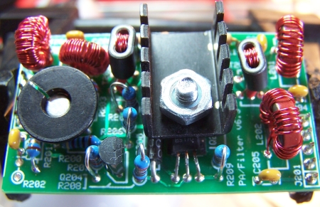
Completed Board (PAF-2: 80/40m)
Testing
Power Rail Resistances
- Plug the PAF board into Jacks J1/J2 and the BPF board into jacks J3/J4
- +12 V testpoint should be very high (> 1 M Ohm) WRT ground.
Your Measurement: _____________________
Current Limited Power Test
- Connect a 100 ohm resistor in series with the power line and apply 12 V dc power
- the current should be less than 120 mA
- Measure the voltage WRT ground at the +5 V and at the 3.3 Vdc testpoints.
- A voltage of around 2 V dc indicates the power rails are not shorted
- Remove the current-limiting resistor. Subsequent tests in this stage are with the current-limiting resistor OUT of the circuit.
Current Draw (Power drain)
- without limiting resistor you should see < 100 mA.
Your Measurement: _____________________
PTT Current Draw
PTT input function may be verified by connecting PTT input line, (I PTT), to 12 volts. (Exercise care in connecting 12 volts to the PTT input line because a connection of 12 volts to the PTT output line, (PTT O), can damage U3.)- Before powering up, attach a clip lead between a 12 volt point1 and the "PTT-I"
(this sets PTT_IN = 12 Vdc, ON)
Be careful. Do not apply 12Vdc to the terminal marked "PTT-O" - it causes chips to fry!
- Apply power
- Measure current draw (should be less than 200 mA (1.92 W)).
Your Measurement: _____________________
PA Standing Current
PA standing current is checked by connecting PTT-in to 12 volts and measuring the voltage across resistors R210 and R211. The DC voltage across each resistor should be 55 mVDC +/- 10mVDC.
- Before powering up, attach a clip lead between a 12 V point1 and the "PTT-I"
(this sets PTT_IN = 12 Vdc, ON)
Be careful. Do not apply 12Vdc to the terminal marked "PTT-O" - it causes chips to fry!
- Apply power
- Measure the dc voltage across R210 (nominal is ~55 mVdc +/- 10 mVdc).
Your Measurement: _____________________ - Measure the dc voltage across R211 (nominal is ~55 mVdc +/- 10 mVdc).
Your Measurement: _____________________ - Measure the dc voltage (forward bias) at the junction of R204 and R205 (nominal is ~2.2 Vdc).
Your Measurement: _____________________
Receiver Test
This test will use the Rocky SDR program and will test the receiver with the local oscillator switch set to 0100 (center frequency of 7.046 MHz)
The RX antenna connection on the v6.3 board is through the TX LP filter. Thus an appropriate PA/Filter board needs to be plugged on top of the RXTX board, or if no PA/Filter board is plugged in, a jumper needs to be placed between pins 1 and 5 of J2 on the RXTX board.
- Connect the line-in cable to a soundcard line-in jack (or Mic-In if no Line-In)
- Connect a 50 ohm antenna through a coaxial cable to the board
- plug in the proper BPF board (or short pins 1 and 5 of J2)
- Connect DC power to the board.
- Set up Rocky for receiving. In view settings, on the "Audio" tab:
- IQ Input Device: select your sound card as the IQ Output Device
- sampling rate: select your desired sampling rate
- Shift Right Channel Data by: select the appropriate number of samples to shift the right channel (if you are not sure, start out with a shift of zero samples)
- Audio Output Deviceselect the sound card to be used for the human-audible output of the SDR
- The example below shows the author's settings. It selects the Soundblaster Live 24 bit USB external soundcard for the IQ heavy lifting and the on-board soundcard for the audible results.
-
- If you have not already done so, set up Rocky's .ini file to program Rocky for the center frequencies corresponding to the settings of SW1.
- Start Rocky (File/Start Radio) and power up the board
- Select the desired center frequency (our example = 7.046 MHz)
-
- Connect the Antenna to a signal source and
generate a signal at about 7.040 MHz:
- (the author has used the Norcal S9 Signal Generator, which generates a 50 uV crystal-controlled signal at 7.040 MHz).
- You can use your transceiver as a signal source by loosely coupling the Softrock's antenna to the QRP output of the transceiver into a dummy load.
- You should see signals in Rocky's default spectrum view:
- In addition, you can loosely couple the antenna input to a signal generator and sweep the frequencies around the center frequency. In this instance, you should see the signal march across Rocky's spectrum display. It's actually pretty neat, even psychodelic, in a geeky sort of way.
- If you see an image that is a mirror image of the signal, refer to the image rejection hints on this site.
RF Output
A quadrature audio source can be used for initial testing of the transmit function. Quadrature audio can be provided from a PC soundcard line-out if a program such as IQ GEN by DL6IAK or Rocky is installed on the PC.Note: on the author's PC, IQ Gen was unable to produce the required 2.4 V p-p signals needed to drive the transmitter to its full 1 W output. However, it still serves as a means to produce an adjustable level of I and Q signals for initial tests.
TX Output Test
PA Output Test - No Scope
- Use the same Rocky setup from above
- Set up Rocky to transmit (i.e., send out I and Q signals) .
-
- Connect the soundcard's Line Out to the "L" and "R" pads on the board
- Connect your antenna terminals to a 50 ohm load - for illustration we are using the Norcal Dummy Load
- Power up the RXTX with PTT-I at 12 V
- During testing, take care not to leave the Softrock at PTT=high for any length of time - the heat sink and the PA FETs will get uncomfortable hot if you do!
- Set the center frequency of Rocky accordingly and, using your mouse, select a frequency on the spectrun display approximetaly 15 kHz above the center frequency (7.061 MHz when SW1 is set for a center frequency of 7.046 MHz. Click on the "TX" button at the top of the screen, select "Tone" to get a single sine wave out of the PC's sound card (I and Q) outputs.
-
- Check for DC voltage at the 50 ohm dummy load's DC output as RoCheck for DC voltage at the 50 ohm dummy load's DC output as Rocky's IQ Amplitude audio level slider is increased towards max
-
The DC voltage at the 50 ohm load should go to ~10 Vdc, (1 watt output), when the quadrature audio inputs are each at their max.
Author's initial test measured 9.8 Vdc (using a pack of 8 AA cells), which interpolates to slightly over 900 mW. The voltage measured when using a 12V gel cell for power was 10.7 Vdc, just a tad over 1 W.
Your measurement _____________ - Simon N0EPW has observed that if the output power is about 1/2 what it should be, You should check the installation of T201 or T202. He found this out the hard way. Of course the first tranformer he removed was the good one :-(
PA Output Test - Scope
(Usual caveats as to author's scope's accuracy and stability apply here)- Use the same Rocky setup from above with the board powered up and PTT-I high
- Click on Rocky's "TX" button and transmit a tone
- check for RF output across the 50 ohm load as Rocky's IQ Amplitude audio level is increased towards max
- The RF voltage across theThe RF voltage across the
50 ohm load should go to ~20V p-p, (1 watt output), when the quadrature audio inputs
are each at 2.4V p-p..
Author's initial measurement 19.35 V p-p using the 8 AA cells; using the 12 V gel cell, the output was 21.6 V p-p
Your Measurement: _____________________ - The RF output waveform across the 50 ohm load should appear as a clean looking sine wave when viewed with a scope. The frequency of the RF voltage should be equal to the center frequency + or - 15 kHz where the + or - frequency offset depends on the line-out signal phase relationship between the two line-out channels.
- The example shown below has the correct wave form and frequency, but the V p-pand frequency are approximate (however this may well be due to the calibration and accuracy of the author's cheapo scope).
- The power output is derived using the following formula:
[ (Vpk)2 * 0.125 ] / 50
= [ (21.5)2 * 0.125 ] / 50
= 1.16 W (1156 mW)
TX I/Q Balancing
Balance the I and Q outputs of Rocky (phase and gain) for the cleanest image rejection during transmit.
While not actually a "test procedure", the process of TX I/Q Balancing is a last step to enabling a fully functional, optimized TX for the RXTX V6.3 (this applies to use of the RXTX V6.3 with the Rocky software).