Local Oscillator Introduction
General
Note: The crystals included with the Lite II Combined kit are:
- ECS-73-18-4XEN a 7.3728 MHz crystal giving a 160m center frequency of about 1.843 MHz,
- ABLS-14.08919MHZ-10-J4Y a 14.089 MHz crystal giving an 80m center frequency of about 3.522 MHz,
- HC49US-28.224MABJ-UB a 28.224 MHz crystal giving a 40m center frequency of a bout 7.055 MHz,
- HC49US-13.500MABJ-UB a 13.5 MHz crystal giving a 1/3 sub-harmonic sampled 30m center frequency of about 10.125 MHz,
- 18.730 MHz crystal giving a 1/3 sub-harmonic sampled 20m center frequency of about 14.047 MHz.
Theory of Operation
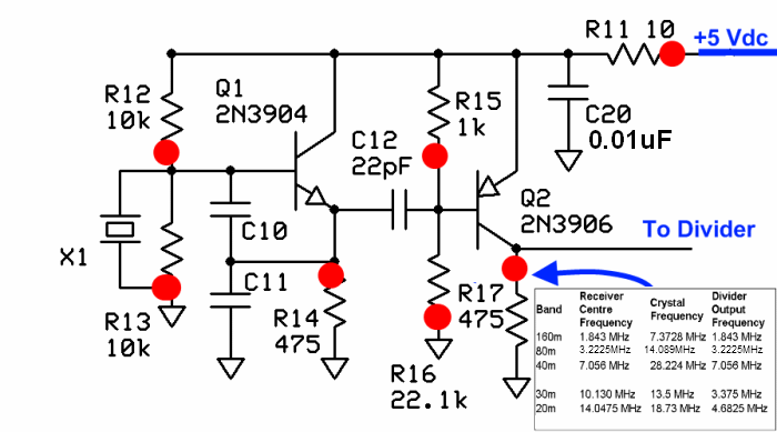
The Local Oscillator stage implements a basic Colpitts Crystal Oscillator with a buffer stage to increase the signal level. The oscillator produces a signal that is at the crystal's specified fundamental frequency.
See the table in the lower right-hand corner of the schematic below for the frequencies produced by this stage, for the appropriate band/kit.
In reality, for each frequency the crystal circuit will oscillate at a slightly lower frequency (~ - 1 kHz), due to the capacitive divider (C10/C11) pulling the crystal down somewhat. The effect is more pronounced for the higher bands.
Sub-harmonic Sampling
Alan, G4ZFQ points out that on the 30m, 20m, 15m receivers, the Local Oscillator produces a signal that is 4/3 times the desired center frequency as opposed to the 4x the center frequency output for the lower band models.
"Subharmonic" works like this:- The LO outputs a 13.5MHz signl that goes to the dividers /4, resulting in 1 3.375MHz square wave ( rich in odd harmonics) being fed to the mixer. At the mixer, a strong 3rd harmonic is present on the clock inputs, along with the fundamental of 3.375 MHz. The 3.375 fundamental multiplied by 3 yields the third harmonic of 10.125MHZ. The Bandpass filter (BPF) performs the essential function of severely attenuating any signals centered around the 3.375MHz fundamental frequency and first harmonmic, but allows 30m signals centering around the third harmonic of the 3.375MHz LO output. The result is that the mixer is dealing with signals in the passband, centering on 10.125MHz, as though the dividers were passing a fundamental frequency of 10.125 to the mixer. BPFs are all that stop Softrocks from working on unwanted frequencies!
Local Oscillator Schematic
(Resistor testpoints (hairpin, top, or left-hand lead), as physically installed on the board, are marked in the schematic with red dots)
(Click for Full Schematic)
(above schematic has clickable areas that can be used for navigation)
(go directly to build notes)Local Oscillator Bill of Materials
Stage Bill of Materials
(resistor images and color codes courtesy of WIlfried, DL5SWB's R-Color Code program)
| Check | Count | Component | Marking | Category |
|---|---|---|---|---|
| ❏ | 1 | 1 k 1/4W 1% | br-blk-blk-br-br
 | 1/4W |
| ❏ | 2 | 10 k 1/4W 1% | br-blk-blk-r-br
 | 1/4W |
| ❏ | 1 | 10 ohm 1/4W 1% | br-blk-blk-gld-br
 | 1/4W |
| ❏ | 1 | 22.1 k 1/4W 1% | r-r-brn-r-br
 | 1/4W |
| ❏ | 2 | 475 1/4W 1% | y-v-grn-bl-br
 | 1/4W |
| ❏ | 1 | 22 pF 5% | 22J
 | Ceramic |
| ❏ | 1 | band-specific | misc | |
| ❏ | 1 | band-specific | misc | |
| ❏ | 1 | band-specific | misc | |
| ❏ | 1 | 0.01 uF | (smt)
 | SMT 1206 |
| ❏ | 1 | 2N3904 NPN Transistor | 2N3904
 | TO-92 |
| ❏ | 1 | 2N3906 PNP transistor | 2N3906
 | TO-92 |
Band Specific Items for 160m Band
| Check | Designation | Component | Marking | Category | Orientation | Notes | Circuit |
|---|---|---|---|---|---|---|---|
| ❏ | C10 | 330 pF 5% | 331
 | Ceramic | Local Oscillator | ||
| ❏ | C11 | 180 pF 5% | 181
 | Ceramic | Not used at all for 40m & 15m versions | Local Oscillator | |
| ❏ | X1 | 7.3728 MHz | ECS-73-18-4XEN | Xtal | Local Oscillator |
Band Specific Items for 80m Band
| Check | Designation | Component | Marking | Category | Orientation | Notes | Circuit |
|---|---|---|---|---|---|---|---|
| ❏ | C10 | 180 pF 5% | 181
 | Ceramic | Local Oscillator | ||
| ❏ | C11 | 100 pF 5% | 101
 | Ceramic | Not used at all for 40m & 15m versions | Local Oscillator | |
| ❏ | X1 | 14.089 MHz | ABLS-14.08919MHZ-10-J4Y | Xtal | 6_10_2010 | Local Oscillator |
Band Specific Items for 40m Band
| Check | Designation | Component | Marking | Category | Orientation | Notes | Circuit |
|---|---|---|---|---|---|---|---|
| ❏ | C10 | 100 pF 5% | 101
 | Ceramic | Local Oscillator | ||
| ❏ | C11 | unused capacitor | Unused | Not used at all for 40m & 15m versions | Local Oscillator | ||
| ❏ | X1 | 28.224 MHz | HC49US-28.224MABJ-UB | Xtal | Local Oscillator |
Band Specific Items for 30m Band
| Check | Designation | Component | Marking | Category | Orientation | Notes | Circuit |
|---|---|---|---|---|---|---|---|
| ❏ | C10 | 180 pF 5% | 181
 | Ceramic | Local Oscillator | ||
| ❏ | C11 | 100 pF 5% | 101
 | Ceramic | Not used at all for 40m & 15m versions | Local Oscillator | |
| ❏ | X1 | 13.5 MHz | HC49US-13.500MABJ-UB | Xtal | Local Oscillator |
Band Specific Items for 20m Band
| Check | Designation | Component | Marking | Category | Orientation | Notes | Circuit |
|---|---|---|---|---|---|---|---|
| ❏ | C10 | 180 pF 5% | 181
 | Ceramic | Local Oscillator | ||
| ❏ | C11 | 100 pF 5% | 101
 | Ceramic | Not used at all for 40m & 15m versions | Local Oscillator | |
| ❏ | X1 | 18.73 MHz | 18.730 1108 | Xtal | Local Oscillator |
Local Oscillator Summary Build Notes
- Install SMT cap
- Install Crystal
- Install Ceramic Capacitors
- Install transistors
- Install Resistors
- Test the Stage
Local Oscillator Detailed Build Notes
Bottom of the Board

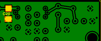
Install SMT cap
See hints on installing SMT Caps.
| Check | Designation | Component | Marking | Category | Orientation | Notes |
|---|---|---|---|---|---|---|
| ❏ | C20 | 0.01 uF | (smt)
 | SMT 1206 |
Top of the Board

Install Crystal
See Band-specific Components chart for value.
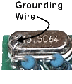
Mount the HC49 crystal mounting in the upper left corner of the board, mounting it vertically to the board. A small plated-through hole in the lower left corner of the crystal mounting position provides a place for a grounding wire to be soldered to the metal crystal case. The grounding wire also provides additional mechanical support for the crystal.
Make sure the crystal is mounted slightly above the board. You can use a piece of cardboard or wire insulation between the bottom of the crystal and the board to get the desired standoff distance while mounting X1. This can help prevent the two plated holes beneath the crystal from shorting out on the crystal case.

| Check | Designation | Component | Marking | Category | Orientation | Notes | ||||||||||||||||||
|---|---|---|---|---|---|---|---|---|---|---|---|---|---|---|---|---|---|---|---|---|---|---|---|---|
| ❏ | X1 | band-specific |
| misc |
Install Ceramic Capacitors
See Band-specific Capacitors chart for value.
See hints on identifying and installing Ceramic Capacitors.

| Check | Designation | Component | Marking | Category | Orientation | Notes | ||||||||||||||||||
|---|---|---|---|---|---|---|---|---|---|---|---|---|---|---|---|---|---|---|---|---|---|---|---|---|
| ❏ | C12 | 22 pF 5% | 22J
 | Ceramic | ||||||||||||||||||||
| ❏ | C10 | band-specific |
| misc | ||||||||||||||||||||
| ❏ | C11 | band-specific |
| misc | Not used at all for 40m & 15m versions |
Install transistors
Mount the two transistors being careful to orient them according to the pattern in the silkscreen.
Take care not to get 2N3904 and 2N3906 mixed up. Carefully check the last digit.

| Check | Designation | Component | Marking | Category | Orientation | Notes |
|---|---|---|---|---|---|---|
| ❏ | Q1 | 2N3904 NPN Transistor | 2N3904
 | TO-92 | ||
| ❏ | Q2 | 2N3906 PNP transistor | 2N3906
 | TO-92 |
Install Resistors
See hints on installing and orienting resistors

| Check | Designation | Component | Marking | Category | Orientation | Notes |
|---|---|---|---|---|---|---|
| ❏ | R11 | 10 ohm 1/4W 1% | br-blk-blk-gld-br
 | 1/4W | W-E | |
| ❏ | R14 | 475 1/4W 1% | y-v-grn-bl-br
 | 1/4W | E-W | |
| ❏ | R17 | 475 1/4W 1% | y-v-grn-bl-br
 | 1/4W | E-W | |
| ❏ | R15 | 1 k 1/4W 1% | br-blk-blk-br-br
 | 1/4W | N-S | |
| ❏ | R12 | 10 k 1/4W 1% | br-blk-blk-r-br
 | 1/4W | E-W | |
| ❏ | R13 | 10 k 1/4W 1% | br-blk-blk-r-br
 | 1/4W | E-W | |
| ❏ | R16 | 22.1 k 1/4W 1% | r-r-brn-r-br
 | 1/4W | N-S |
Local Oscillator Testing
Visual Check
Test Setup
Using very good lighting and magnification, carefully inspect the solder joints to identify bridges, cold joints, or poor contacts.Current Draw
Test Setup
- connect a 1k ohm resistor in series with the positive power lead
- apply 12 Vdc and measure the current draw with the limiting resistor in place
- remove the current limiting resistor
- apply 12 Vdc and measure the current draw without the limiting resistor
Test Measurements
| Testpoint | Units | Nominal Value | Author's | Yours |
|---|---|---|---|---|
| With the 1k limiting resistor | mA | < 9 | 7.3 | _______ |
| Without current limiting resistor | mA | < 20 | 14.1 | _______ |
Voltage Tests
Test Setup
- Power the board
- Measure the testpoint voltages with respect to ground
Note that some of the voltages measured may have ac components, which, depending upon your DMM, may average in with the dc voltages to produce higher apparent dc voltages than theory would suggest.
Author measured the dc voltage at R17 using a scope and got ~2.6 Vdc. Per Alan, G4ZFQ, This voltage (at R17) is not critical and can vary a lot, partly depending on the crystal. The important thing is that the LO's RF output is a good healthy signal and is detectable on an external RX (or counter or scope).
Test Measurements
| Testpoint | Units | Nominal Value | Author's | Yours |
|---|---|---|---|---|
| R11 hairpin | Vdc | 4.5 - 5 | 4.9 | _______ |
| R15 hairpin | Vdc | < R11 hairpin | 4.7 | _______ |
| R12 hairpin | Vdc | < 2.5 | 2.3 | _______ |
| R17 hairpin | Vdc | > 2.0 | 4.2 | _______ |
LO Output Test
Test Setup
- On the 3 lower bands, the frequency of the LO’s output should be 4 times the desired center frequency e.g., 28.224 MHz for a desired center frequency of 7.056 MHz).
- If your kit is the 30m, 20m, or 15m kit, this is a little different. The higher band SoftRock Lite kits use 1/3 sub-harmonic sampling to give receive function. The center frequency is approximately 3 * XtalFrequency / 4 in MHz. The loss in sensitivity associated with the 1/3 sub-harmonic sampling, about 3 or 4 dB, is made up by 5x gain, (compared to the lower band SoftRock Lite kits), in the I / Q audio stage where a low-noise LT6231 op-amp is used in lieu of the TVL2462CD opamps
- The crystal frequency is band-specific, as follows:
| Designation | Band | Frequency |
|---|---|---|
| X1 | 160m | 7.3728 MHz |
| X1 | 80m | 1489 MHz |
| X1 | 40m | 28.224 MHz |
| X1 | 30m | 13.5 MHz |
| X1 | 20m | 18.73 MHz |
| X1 | 15m | 28.06 MHz |
- You can use a ham receiver tuned to the appropriate crystal frequency. You should hear the LO's frequency.
- Scope measurements may be taken IF you have a high quality, calibrated scope with correctly compensated probes
- Note: 1/3 sub-harmonic sampling does reverse the spectrum. Changing the audio cable connections to the SoftRock Lite circuit board from tip to ring and ring to tip will correct the reversed spectrum so that the SDR software works the same for the higher band receivers as with the lower band receivers. (See Cecil K5NWA'a explanation of the sub-harmonic sampling in his message on the Yahoo Softrock group.
 LO Output Test"


