Mixer Introduction
General
From the builder's standpoint, the Mixer stage consists solely of the installation of the input resistors (R1 and R2) and the integrating capacitors, C5 and C6. The installation of the IC, U3, was performed in the Dividers Stage.
Theory of Operation
The RF input signal, filtered by the BPF is applied in antiphase to the inputs 1B and 2B of the Mixer U3.
The two LO signals from the Divider Stage operate the switches which connect R1 to C5 and connects R2 to C6 during the first clock cycle.
When the LO Clock changes 90 degrees later, the connections reverse: R1 now connects to C6 (Q) and R2 connects to C5 (I).
This switching sequence then repeats itself.
The resulting RF input signal is sampled over capacitors C5 and C6 as the Intermediate Frequency (IF)
On the lower bands (160m, 80m, and 40m) the dividers are clocked at the desired center frequency, which is in the pass band for the incoming RF.
On the higher bands, the situation in the Softrocl RX is a little different. The clocking frequency is at the one-third sub harmonic of the desired center frequency and is NOT within the passband of the incoming RF.
For example, consider the 20m RX:
- For 20m, the dividers are clocked at about 18.73 MHz and their output QSD clock is 18.73 MHz / 4 = 4.682 MHz
- The third harmonic of that clock frequency is 3 * 4.682 = 14.047 MHz.
- The 20m signals in the BPF's passband will be sampled at that 3rd harmonic; however, the sampling will not yield as strong an I/Q pair as does the sampling technique used in the lower bands. Hence, the higher gain OpAmps for the higher band kits.
- It is like looking at a rotating wheel with a strobe flashing once for every three revolutions of the wheel. The rotation speed of the wheel is down converted but the image is not as bright as it would be if you flashed the strobe at the rotation speed of the wheel.
If you are interested, you might want to review the "Tayloe Mixer" operation. While the Softrock mixer is not a pure Tayloe mixer, the theoretical discussion on Taylo mixers helps with understanding how this process works.
Mixer Schematic
(Resistor testpoints (hairpin, top, or left-hand lead), as physically installed on the board, are marked in the schematic with red dots)
(Click for Full Schematic)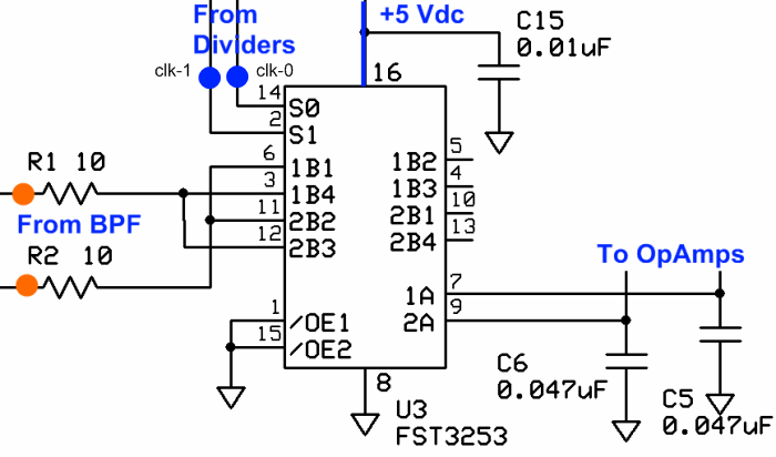
(above schematic has clickable areas that can be used for navigation)
(go directly to build notes)Mixer Bill of Materials
Stage Bill of Materials
(resistor images and color codes courtesy of WIlfried, DL5SWB's R-Color Code program)
| Check | Count | Component | Marking | Category |
|---|---|---|---|---|
| ❏ | 2 | 10 ohm 1/4W 1% | br-blk-blk-gld-br
 | 1/4W |
| ❏ | 2 | 0.047 uF 5% | 473
 | Ceramic |
Mixer Summary Build Notes
- Install Topside Components
- Test the Stage
Mixer Detailed Build Notes
Bottom of the Board
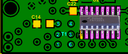
Top of the Board
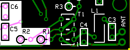
Install Topside Components
Install R1 and R2
See hints on orienting and installing resistorss.
Install integrating capacitors, C5 and C6
See hints on identifying and installing Ceramic Capacitors.
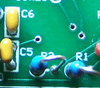
| Check | Designation | Component | Marking | Category | Orientation | Notes |
|---|---|---|---|---|---|---|
| ❏ | R01 | 10 ohm 1/4W 1% | br-blk-blk-gld-br
 | 1/4W | W-E | |
| ❏ | R02 | 10 ohm 1/4W 1% | br-blk-blk-gld-br
 | 1/4W | W-E | |
| ❏ | C05 | 0.047 uF 5% | 473
 | Ceramic | vert | |
| ❏ | C06 | 0.047 uF 5% | 473
 | Ceramic | vert |
Mixer Testing
Warning
Test Setup
Take appropriate ESD precautions in these tests, since you will be working around the very sensitive mixer ICVisual Inspection
Test Setup
Using very good lighting and magnification, carefully inspect the solder joints to identify bridges, cold joints, or poor contacts.
Pay especial attention to the joints on the Mixer IC pins. If necessary, touch up the joints with your iron and/or some flux. Wick up any excess.
Current Draw
Test Setup
- In each test, the ammeter must be placed in series between the positive lead of the power source and the board's positive power-in "+" terminal.
- In one test there is also a 100 ohm resistor in the series "chain" as well.
- in the second test, the setup is the same except that the 100 ohm current-limiting resistor is removed
- The mixer stage should not appreciably change the current draw from preceding stages.
Apply 12 Vdc to the board for this test
Test Measurements
| Testpoint | Units | Nominal Value | Author's | Yours |
|---|---|---|---|---|
| With the 100 ohm current limiting resistor | mA | < 30 | 26.1 | _______ |
| Without the current limiting resistor | mA | < 30 | 26.4 | _______ |
Voltage Tests
Test Setup
Power up the board and measure the pin voltages with respect to ground (on the pins, not the pads) of U3, per the table below
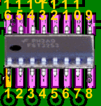
Test Measurements
| Testpoint | Units | Nominal Value | Author's | Yours |
|---|---|---|---|---|
| Pin 14 (QSD clk_0 on topside) | Vdc | 2.5 | 2.47 | _______ |
| Pin 2 (QSD clk_1 on topsode) | Vdc | 2.5 | 2.47 | _______ |
| Pins 3 & 12 | Vdc | 2.3 - 2.5 | 2.44 | _______ |
| Pins 6 & 11 | Vdc | 2.3 - 2.5 | 2.44 | _______ |
| Pin 7 (1A) | Vdc | 2.3 - 2.5 | 2.44 | _______ |
| Pin 9 (2A) | Vdc | 2.3 - 2.5 | 2.44 | _______ |
| Pin 16 | Vdc | 5 | 4.94 | _______ |
| Pin 8 | Vdc | 0 | 0 | _______ |
| Pins 1 & 15 | Vdc | 0 | 0 | _______ |