Band Pass Filter Introduction
General
 Remember, when winding toroidal inductors, a single pass through the core counts as 1 turn. You might want to review
Leonard KC0WOX's excellent 10-minute video on winding toroidal coils and transformers.
Also, please refer to the common component mounting instructions for toroids
Theory of Operation
The purpose of this stage is to pass the Radio Frequency signals within the receiver band to the mixer stage and to attenuate unwanted signals which are not within the designed passband for the filter.
This attenuation is especially important, since it permits the 1⁄3 harmonic sampling in the mixer for the higher bands. Without that attenuation, for example, the 20m kit would be responding to signals in the region of 4.6825 MHz rather than to the designed response in the region of the 3rd harmonic of 14.0475 MHz!
For further information on the subharmonic sampling effect, refer to this topic on the Yahoo Reflector.
Band Pass Filter Schematic
(Resistor testpoints (hairpin, top, or left-hand lead), as physically installed on the board, are marked in the schematic with red dots)
(Click for Full Schematic)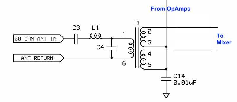
(above schematic has clickable areas that can be used for navigation)
(go directly to build notes)Band Pass Filter Bill of Materials
Stage Bill of Materials
(resistor images and color codes courtesy of WIlfried, DL5SWB's R-Color Code program)
| Check | Count | Component | Marking | Category |
|---|---|---|---|---|
| ❏ | 4 | band-specific | misc | |
| ❏ | 2 | T30-6 toroid core | yellow
 | Toroid |
Band Specific Items for 160m Band
| Check | Designation | Component | Marking | Category | Orientation | Notes | Circuit |
|---|---|---|---|---|---|---|---|
| ❏ | C03 | 390 pF 5% | 391
 | Ceramic | Band Pass Filter | ||
| ❏ | C04 | 5600 pF 5% | 562 | Ceramic | Band Pass Filter | ||
| ❏ | L1 | 19.6 uH 74T #30 on T30-6 (yellow) (38") | yellow
 | Coil | 38" | Band Pass Filter | |
| ❏ | T1 | 1.4 uH 20T/10T bifilar #30 on T30-6 (yellow) (13") | yellow
 | Xfrmr | Band Pass Filter |
Band Specific Items for 80m Band
| Check | Designation | Component | Marking | Category | Orientation | Notes | Circuit |
|---|---|---|---|---|---|---|---|
| ❏ | C03 | 220 pF 5% | 221
 | Ceramic | Band Pass Filter | ||
| ❏ | C04 | 3300 pF 5% | 332 | Ceramic | Band Pass Filter | ||
| ❏ | L1 | 9.1 uH 50T #30 on T30-6 (yellow) (26") | yellow
 | Coil | 26" | Band Pass Filter | |
| ❏ | T1 | 0.73 uH 14T/7T bifilar #30 on T30-6 (yellow) (10") | yellow
 | Xfrmr | Band Pass Filter |
Band Specific Items for 40m Band
| Check | Designation | Component | Marking | Category | Orientation | Notes | Circuit |
|---|---|---|---|---|---|---|---|
| ❏ | C03 | 100 pF 5% | 101
 | Ceramic | Band Pass Filter | ||
| ❏ | C04 | 1500 pF 10% | 152
 | Ceramic | Band Pass Filter | ||
| ❏ | L1 | 5.0 uH 37T #30 on T30-6 (yellow) (20") | yellow
 | Coil | 20" | Band Pass Filter | |
| ❏ | T1 | 0.35 uH 10T/5T bifilar #30 on T30-6 (yellow) (8") | yellow
 | Xfrmr | Band Pass Filter |
Band Specific Items for 30m Band
| Check | Designation | Component | Marking | Category | Orientation | Notes | Circuit |
|---|---|---|---|---|---|---|---|
| ❏ | C03 | 68 pf 5% | 68J | Ceramic | Band Pass Filter | ||
| ❏ | C04 | 1000 pF 5% | 102
 | Ceramic | Band Pass Filter | ||
| ❏ | L1 | 3.5 uH 31T #30 on T30-6 (yellow) (17") | yellow
 | Coil | 17" | Band Pass Filter | |
| ❏ | T1 | 0.18 uH 8T/4T bifilar #30 on T30-6 (yellow) (7") | yellow
 | Xfrmr | Band Pass Filter |
Band Specific Items for 20m Band
| Check | Designation | Component | Marking | Category | Orientation | Notes | Circuit |
|---|---|---|---|---|---|---|---|
| ❏ | C03 | 47 pF 5% | 47J | Ceramic | Band Pass Filter | ||
| ❏ | C04 | 680 pF 5% | 681
 | Ceramic | Band Pass Filter | ||
| ❏ | L1 | 2.5 uH 26T #30 on T30-6 (yellow) (15") | yellow
 | Coil | 15" | Band Pass Filter | |
| ❏ | T1 | 0.18 uH 8T/4T bifilar #30 on T30-6 (yellow) (7") | yellow
 | Xfrmr | Band Pass Filter |
Band Pass Filter Summary Build Notes
- Install Band-specific Capacitors
- Wind and Install Band-specific L1
- Wind and Install band-specific T1
- Test the Stage
Band Pass Filter Detailed Build Notes
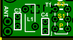
Bottom of the Board
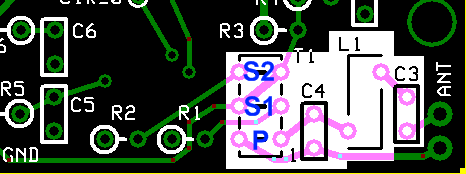
Top of the Board
Install Band-specific Capacitors
Install the band-specific capacitors, C3 and C4.
See band-specific chart for values
See hints on identifying and installing Ceramic Capacitors.
| Check | Designation | Component | Marking | Category | Orientation | Notes | ||||||||||||||||||
|---|---|---|---|---|---|---|---|---|---|---|---|---|---|---|---|---|---|---|---|---|---|---|---|---|
| ❏ | C03 | band-specific |
| misc | ||||||||||||||||||||
| ❏ | C04 | band-specific |
| misc |
Wind and Install Band-specific L1
Install the band-specific coil, L1.
Also, please refer to the common component mounting instructions for toroids
Band-Specific Details
L1, for all bands, uses #30 wire and T30-6 toroid core. Turn counts, wire lengths, and inductance per band are shown in the table below:
| Band | Core | Length | Turns | µH |
|---|---|---|---|---|
| 160m | T30-6 (yellow) | 38" | 74 | 19.6 |
| 80m | T30-6 (yellow) | 26" | 50 | 9.1 |
| 40m | T30-6 (yellow) | 20" | 37 | 5.0 |
| 30m | T30-6 (yellow) | 17" | 31 | 3.5 |
| 20m | T30-6 (yellow) | 15" | 26 | 2.5 |
BOM Notation
Wind the band-specific number of turns of #30 wire onto the band-specific toroidal core. E.G., "9.1 uH 50T #30 on T30-6 (yellow) (26")" means use 26 inches of #30 wire to wind 50 turns onto a T30-6 toroidTurn Counting
Each pass through the center of the core is counted as a turn when winding the inductor.Do you Run Out of Toroid Before You Run Out of Turns?
Occasionally, you may find that there is not enough room on the toroid toplace all of the windings without having to go back and add a layer of winding. Tony Parks suggests that you overlap some turns as you put on windings around the circumference of the core so that all turns are on the core by the time you get back to the start end of the winding. This should have negligible effect on the coil's performance in the radio.Coil Orientation
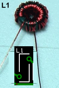
L1 is mounted vertically and supported by its leads.Lead Preparation
Be sure to remove the enamel coating on the wire before attempting to solder an inductor lead to its associated mounting hole. There are two different approaches to removing the enamel and tinning the leads:- The enamel coating on the #30 wire provided in the kit does not heat strip very well but may be stripped by use of a small folded over piece of Emory paper where the lead is pulled through two facing surfaces of the Emory paper multiple times to sand off the enamel coating on the wire end. Then you can run each lead through a blob of solder on the hot iron tip to tin it.
- If you have some solder flux (I use the paste kind), you can slather each lead with flux paste and then run each lead through a hot blob of solder to clean and tin the tip. You may have to repeat the process a couple of times to get all the gunk off of the lead. It produces a well-tinned lead with non of the trauma inherent in stripping the enamel with sandpaper or exacto knife.
| Check | Designation | Component | Marking | Category | Orientation | Notes | ||||||||||||||||||
|---|---|---|---|---|---|---|---|---|---|---|---|---|---|---|---|---|---|---|---|---|---|---|---|---|
| ❏ | L1 | band-specific |
| misc |
Wind and Install band-specific T1
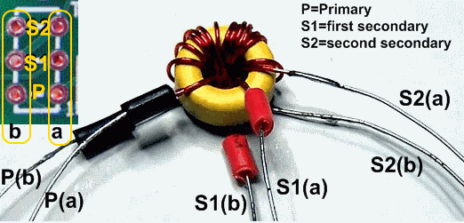
If T1 is not wired correctly to the six holes on the Lite circuit board it can result in very low receiver sensitivity. You should carefully read this section and study the photo below showing how to mount the transformer.
Also, please refer to the common component mounting instructions for toroids and detailed instructions for T1 in the 20m SR Lite II kit. These resources should help the first-time transformer/coil builder past any concerns in that area.
Band-Specific Transformer Details
The transformer is wound with a primary winding and two secondary windings. The two secondary windings are created by folding the specified length of wire over double ("bifilar") and winding the doubled wire the required number of (secondary) turns. See table below for Core, Length, Turns, and Primary Inductance info. ("Turns 10/5" Means primary is 10 turns and secondaries are 5 turns bifilar):Band Core Length Turns(p/s) µH(p) 160m T30-6 (yellow) 13" 20/10 1.4 80m T30-6 (yellow) 10" 14/7 0.73 40m T30-6 (yellow) 8" 10/5 0.35 30m T30-6 (yellow) 7" 8/4 0.18 20m T30-6 (yellow) 7" 8/4 0.18 BOM Notation
The winding details will be in the form: "nnT/2 x mmT bifilar #30" on Txx-x (LL")". This translates to:- Using a toroid Txx-x and LL inches of #30 wire, wind a primary with nn turns
- then, using the same length of #30 wire folded in half, wind the 2 secondaries on top of the primary for mm turns
Primary Winding
The primary winding is of the band-specific number of turns. Wind the primary winding with the specified number of turns of #30 AWG enameled wire so that the primary winding starts and ends at about the same point on the core and is uniformly spread around the core.Secondary Windings
The secondary uses lengths of #30 wire, twisted together into a bifilar pair that has approximately 2-3 twists per inch and is wound over the primary, using the band-specific number of turns.Wind the secondary windings, in the same direction as the primary, with the windings starting and ending just slightly clockwise around the core from where the primary winding starts and ends.ID and Tag the Winding Leads
After striping and tinning each transformer lead at about 1/8 of an inch from the core, determine the two pairs of leads of each of the secondary windings by use of an ohmmeter. I like to use short lengths of insulation from hookup wire to identify two of the 3 sets of leads in these transformers.Transformer Orientation
(Refer to the graphic, below): Correct wiring is with leads from one side (the "a" side) of the core going to a group of three holes and the leads from the other side (the "b" side) of the core going to the other group of three holes as shown below.- Note the photo below shows the holes for the primary ("P") and each of the two secondary ("S") leads, with the "a" and "b" designating from which side of the core the particular winding's lead should go.
- for example:
- The primary winding's "b" lead would go into the left-hand "P" hole
- The primary winding's "a" lead would go into the right-hand "P" hole
- The first secondary winding's "b" lead would go into the left-hand "S" hole in the middle row of winding holes
- The first secondary winding's "a" lead would go into the right-hand "S" hole in the middle row of winding holes
- and so on …
- Be careful when threading the leads through the holes to avoid their getting tangled up with nearby components!
| Check | Designation | Component | Marking | Category | Orientation | Notes | ||||||||||||||||||
|---|---|---|---|---|---|---|---|---|---|---|---|---|---|---|---|---|---|---|---|---|---|---|---|---|
| ❏ | T1 | band-specific |
| misc |
Band Pass Filter Testing
Visual Check
Test Setup
Using very good lighting and magnification, carefully inspect the solder joints to identify bridges, cold joints, or poor contacts.
Pay especial attention to the joints on the transformer. Bad solder joints in this stage will have an extreme effect on the sensitivity of the receiver.
Inductor Continuity Tests (NO power)
Test Setup
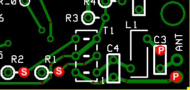
This tests the continuity through L1 and the T1 primary winding, using testpoints (red dot with letter "P") that test the continuity from connected pads. This helps check the soldering of the leads by placing the probes at points that are connected to the actual solder joint.
Similarly, the secondary windings of T1 are tested for continuity, using the secondary testpoints (red dots with the letter "S").
Test Measurements
| Testpoint | Units | Nominal Value | Author's | Yours |
|---|---|---|---|---|
| Point "P" to point "P" | ohm | 0 | 0 | _______ |
| Point "S" to point "S" | ohm | 0 | 0 | _______ |
Voltage Tests
Test Setup
Apply power and measure the voltages WRT (with respect to ground).Test Measurements
| Testpoint | Units | Nominal Value | Author's | Yours |
|---|---|---|---|---|
| R1 hairpin (hole) | Vdc | ~2.5 | 2.47 | _______ |
| R2 hairpin (hole) | Vdc | ~2.5 | 2.47 | _______ |
Resistance Tests (no power)
Test Setup
Remove power from the board and measure the resistance with respect to ground for the T1 secondaries in situ.Test Measurements
| Testpoint | Units | Nominal Value | Author's | Yours |
|---|---|---|---|---|
| R1 hairpin (hole) | ohms | ~800 | 803 | _______ |
| R2 hairpin (hole) | ohms | ~800 | 803 | _______ |
Phasing Test (NO power)
Test Setup
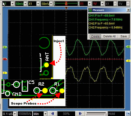
Optional Test - assuming you have a dual channel scope and an RF source that can output a signal close to the band-specific center frequency.
- Conduct this test with the power OFF
- Connect a ~2 volt p-p signal source at around the center frequency into the ANT-IN and RET pads.
- Set up the scope for triggering on Channel 1 .
- Connect the scope probes to the R1 and R2 hairpins (holes) and the ground clips to ground.
- You should have a pair of equal amplitude, opposite phase signals displayed. If they are in phase, you probably aren't triggering the scope on channel 1. If either one is missing, double check the solder connections for T1.
- Thanks to Leonard KC0WOX for this test
