External Connections Introduction
General
The final stage involves connecting the RX to the outside world. Specifically, we need to provide for:
- Power - the power leads can connect to a well filtered, regulated DC source fromn 9 to 13 Vdc.
- RF - need to connect the antenna and antenna return terminals to a 50 ohm antenna tuned for the specified band
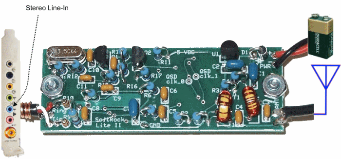
- I/Q Output - connect the I and Q audio outputs of the RX into the PC via the stereo input of its sound-card. Normally, this will connect to the stereo "line-in" jack; depending upon the PC/Laptop, you might need to use the stereo "MIC" jack.
Ground Loops
If your display shows numerous peaks/spikes up and down the spectrum, these are likely caused by ground loops (since the spectrum is a display of I and Q signals in the audio/near-audio range).
Doug, WA3DSP, advises:
The SoftRock boards have a number of places where you could create a ground loop. The antenna should not be one of them as long as you isolate BOTH sides of the connection. In other words do not use a shell grounded BNC or other coax fitting on a metal chassis. I use an isolated shell BNC. The power connection is another place where a ground loop could take place. Of course running on a battery would eliminate that as would powering from a wall transformer.
The only two things left are the audio connections and the USB connection, if you use it. Both are grounded at the computer so in most cases a ground loop would not happen here.
So first make sure you antenna and power to the Softrock card are isolated. You don't need USB to receive so you could disconnect that. Then you would only have one grounded connection to the card and if you are still having problems it might be something else.
Alan, G4ZFQ, puts it this way:
"Ground loop" says it all. The RX must be connected to the computer by just one ground. The PSU is a common reason, somtimes the antenna. There is no simple answer, as you indicate, different setups seem to have different answers. It should be posssible to greatly reduce the problem but experimenting is the only real answer. Check what is grounded and try disconnecting duplicated ones. Multiple connectionas between the SDR and computer may be acceptable if they are run together. Bad audio cables picking up external noise is another thing to look for.
(go directly to build notes) (go directly to build notes)External Connections Bill of Materials
Stage Bill of Materials
(resistor images and color codes courtesy of WIlfried, DL5SWB's R-Color Code program)
| Check | Count | Component | Marking | Category |
|---|---|---|---|---|
| ❏ | 1 | 2 conductor shielded audio cable | Cable | |
| ❏ | 1 | antenna COAX | Cable | |
| ❏ | 1 | power leads | Cable |
External Connections Summary Build Notes
- Install Power Connection
- Install I/Q Audio Cable Connection
- Install Antenna Connection
- Test the Stage
External Connections Detailed Build Notes
Top of the Board
Install Power Connection
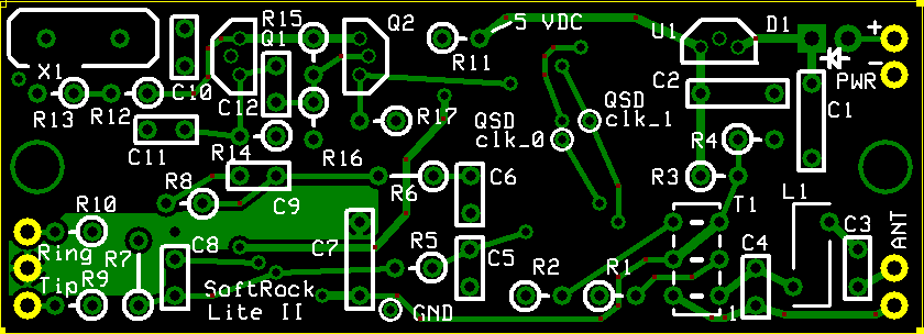
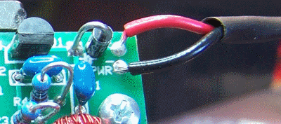
Install the power leads (nominally red for positive and black for negative) to the PWR + and PWR - holes on the upper right-hand side of the board
Use the power jack or plug appropriate to your situation
If at all possible, when initially testing the rig, it would be a good idea to use a battery or gel cell for the power supply. This minimizes the potential (pun intended) for ground loops (see discussion in Introduction section above). Later, you can introduce a mains-powered supply and, if that introduces ground loops, then you can make decisions from that point.
| Check | Designation | Component | Marking | Category | Orientation | Notes |
|---|---|---|---|---|---|---|
| ❏ | pwr | power leads | Cable | not furnished with the kit |
Install I/Q Audio Cable Connection
Cable
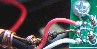
A stereo audio cable may be connected at this time to the board at the three plated through-holes along the lower left edge of the board near the lower left corner.
Strain Relief
Use a short piece of #22 bus wire to connect the middle plated through-hole (ground) to the shield (barrel) of the cable and wrap the end of the bus wire around the outside of the cable several turns for strain relief of the cable.Cable Installation
Notefor the 30m. 20m, and 15m RX kits
1/3 sub-harmonic sampling does reverse the spectrum. Changing the audio cable connections to the SoftRock Lite circuit board from tip to ring and ring to tip will correct the reversed spectrum so that the SDR software works the same for the higher band receivers as with the lower band receivers.- For the lower band units, the tip of the stereo cable plug connects to the plated through-hole that is marked "Tip" on the board. It is the "I" signal. Reverse this for the higher band units.
- For the lower band units, the ring of the stereo cable plug connects to the plated through-hole marked "Ring" and is the "Q" signal. Reverse this for the higher band units.
Alternate Connection - Stereo Jack
Some builders might prefer to implement the I/Q Audio connection using a 1/8" stereo mini-jack instead of a stereo cable terminated with a 1/8" stereo plug. Either approach works and is pretty much up to the individual builder and his/her approach to packaging the finished board.
Troubleshooting Large differences in I and Q Output
The receiver should provide nearly identical I and Q signals (other than phase). If there are significant differences in the gain of each OpAmp output, you may want to look at the following before concluding that the IC is bad:
Things that could affect gain--
- The feedback resistors (R7 and R8) are poorly soldered or of the wrong value(s)
- Incorrectly wound transformer in the BPF.
- Incorrect resistors (10 ohm) at both the input and output of the QSD.
- Incorrect filter capacitor(s) on the output of the QSD.
| Check | Designation | Component | Marking | Category | Orientation | Notes |
|---|---|---|---|---|---|---|
| ❏ | audio | 2 conductor shielded audio cable | Cable | not furnished with the kit |
Install Antenna Connection
Antenna Impedance
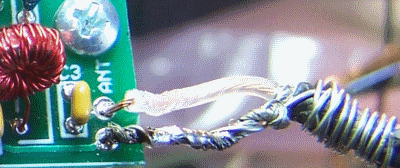
It is extremely important to use an antenna with as close a match as possible to 50 ohms impedance. The radio's sensitivity is predicated on a 50 ohm antenna input.Coax
Connect a length of 50 ohm coax to the antenna connection on the right edge of the board near the lower right corner. RG-174 is a good fit for this tiny board.- The lower of the two plated through-holes is the antenna RTN connection to the coax shield
- The upper plated through-hole is the coax center conductor connection (ANT IN).
Not Grounded!
Note that this connection is isolated from circuit ground.
You may want to review the series of messages on this subJect in the Softrock 40 Yahoo Group.
Additionally, you should review the materials on the Clifton Labs website concerning the use of an antenna isolation transformer
Finally, regarding the "floating antenna RET" connection, review the messages in this topic where the builder was getting no signal and the cause was the improper ANT RET connection.
| Check | Designation | Component | Marking | Category | Orientation | Notes |
|---|---|---|---|---|---|---|
| ❏ | ant | antenna COAX | Cable | not furnished with the kit |
External Connections Testing
Final Test
Test Setup
Once external connections are installed, you are ready to take the radio for a spin. This final test will use Rocky as the SDR Software.
For further discussions of the software side of SDR and soundcard issues, see Alan G4ZFQ's pages.
This test assumes you have the following:- A Windows Computer on which Rocky has been installed.
Note: in Windows Vista, Rocky cannot "see" the on-board soundcard; Rocky can, however, "see" any external USB soundcard connected to a Vista computer. - A sound card with a stereo input ("mic" or "Line-In")
Note: some laptops, unfortunately, lack a true stereo input connection (either no line-in jack or just a "mic" that is mono only). - An antenna (the better the impedance match to 50 ohms, the better the reception)
Setup the Radio and the PC
- Plug the audio output cable into the "mic" or "Line-In" input on the PC's sound card.
- Connect the antenna cable to your antenna (you can use a simple wire antenna, but the reception will be poor).
- Run the Rocky SDR program
-
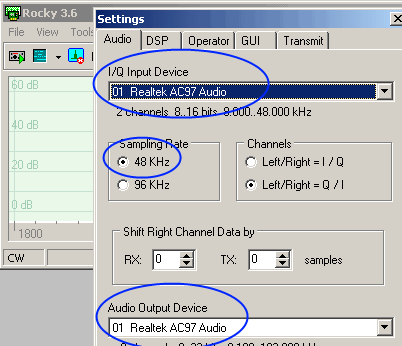
Select your soundcard in Rocky (
View -> Settings -> (click on the "Audio" tab))
Normally, you will have a single soundcard, your on-board card, and that will be the default setting for both the "I/Q Input Device" and the "Audio Output Device". The default sampling rate is 48 kHz (you should be so lucky to have a card that samples at 96 kHz!)
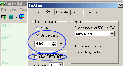
- Set Rocky/s center frequency to the value (in Hz) corresponding to your kit:
- 160m: 1.8432 MHz (1843200 Hz)
- 80m: 3.522 MHz (3522250 Hz)
- 40m: 7.056 MHz (7056000 Hz)
- 30m: 10.125 MHz (10125000 Hz)
- 20m: 14.0475 MHz (14047500 Hz)
- 15m: 21.045 MHz (21045000 Hz)
View -> Settings -> (click on the "DSP" tab))
Example, here, uses 40m rig's center frequency of 7.056 MHz:
- Apply power to the receiver
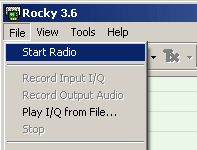
- If not already done, Run Rocky and start the Rocky "radio"
(File > Start Radio- click on "Start Radio")
It's alive, alive I tell you!
View of Rocky Spectrum Centered on 7.056 MHz

If you see an unwanted "mirror image" of the desired signal, you may want to check out the image rejection hints on this website.