Introduction
Not much to say, here. The dividers' contribution to the rig is the reduction of the LO frequency into two signals, each one-quarter of the LO frequency, and in quadrature (i.e., the 2 signals have a 90° phase difference).If this is your first effort at installing SMT ICs, you will want to see the tutorials on SMT soldering and the information on Electrostatic Discharge precautions.
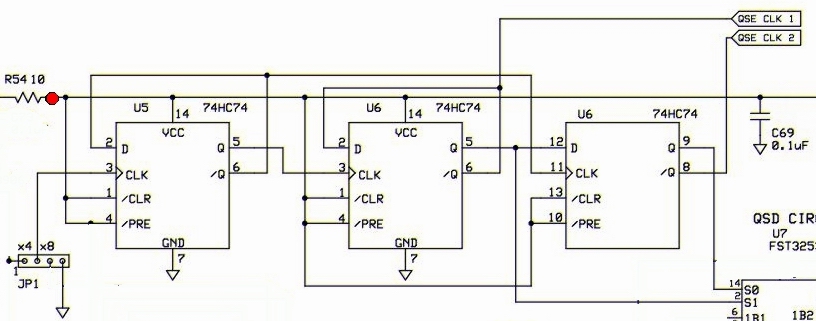
Schematic
Bill of Materials
| Designation | Value | Type | Orientation |
|---|---|---|---|
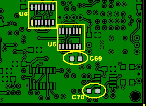
| C69 | 0.1uF | smt 1206 | smt |
| C70 | 0.1uF | smt 1206 | smt |
| U05 | 74HC74 | SOIC 14 | |
| U06 | 74HC74 | SOIC 14 |
Build Notes
Testing
Current Draw
- Initially, place a current limiting 1K resistor in series with one of the power leads,
- apply 12 Vdc power
- measure the current draw.
- You should see less than 10 mA draw (e.g., on the order of 5 to 6 mA). If the draw is greater than 10 mA, you should check your circuit for a short.
- Remove the current limiting resistor
- apply 12 Vdc power
- measure the current draw.
- The result should be around 27 mA.
- Set the ammeter back to voltage
Divider Output Waveforms
- Connect your channel 1 and 2 scope leads to the testpoints shown above (QSE CLK 1 and QSE CLK 2)
- Set the scope trigger to channel 1
- Use the jumper and JP2 to select the 40m Crystal (28.224 or 28.060 MHz).
- Connect the ground clips of the probes to the ground test loop on JP1.
- Power up and observe the traces on the scope.
- Depending upon the crystal selected, you should have a pair of square waves around 5 volts in amplitude and at the desired center frequency. You may see more or less ringing depending on where you hook your probe ground. The waveforms should be "squarish" and 90° out of phase with each other.

(customary disclaimer about scope accuracy)