Introduction
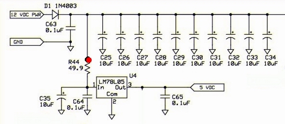
First stage is the power supply. The circuit has 2 power rails:- 12 Vdc power (for the transmitter)
- and 5 Vdc power (for LO and ICs)
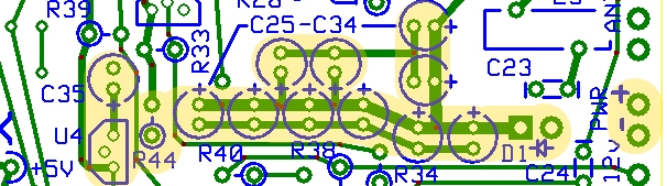
- Ensuring the electrolytic caps are mounted correctly with respect to polarity. The positive lead is the longest lead; the negative lead is identified by a grey marking on the "-" side of the can.
- Mounting the diode D1 corretly with respect to polarity. The anode end (no marking) should be installed snug to the round pad and the cathode end (identified by a band) mounted "hairpin" style into the square pad (see the topside illustration below).
- Soldering the leads on the 5 volt regulator, U4. U4 is mounted to conform to the shape on the board silkscreen, After soldering the leads, double check them for solder bridges.
Schematic
Bill of Materials
| Designation | Value | Orientation | Notes |
|---|---|---|---|
| C25 | 10uF/16 VDC Electrolytic | South-North | |
| C26 | 10uF/16 VDC Electrolytic | South-North | |
| C27 | 10uF/16 VDC Electrolytic | East-West | |
| C28 | 10uF/16 VDC Electrolytic | East-West | |
| C29 | 10uF/16 VDC Electrolytic | North-South | |
| C30 | 10uF/16 VDC Electrolytic | North-South | |
| C31 | 10uF/16 VDC Electrolytic | North-South | |
| C32 | 10uF/16 VDC Electrolytic | North-South | |
| C33 | 10uF/16 VDC Electrolytic | North-South | |
| C34 | 10uF/16 VDC Electrolytic | North-South | |
| C35 | 10uF/16 VDC Electrolytic | South-North | |
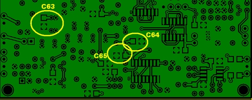
| C63 | 0.1uF smt 1206 | smt | |
| C64 | 0.1uF smt 1206 | smt | |
| C65 | 0.1uF smt 1206 | smt | |
| D1 | 1N4003 | East-West | Mount the diode D1 correctly with respect to polarity. The anode end (no marking) should be installed snug to the round pad and the cathode end (identified by a band) mounted "hairpin" style into the square pad |
| R44 | 49.9, 1/4W, 1% | South-North | |
| U04 | 78L05, 5v voltage regulator | TO 92 |
Build Notes
JP1
Mount a small (sturdy) wire loop in hole 4 of JP1 location to use as a ground test point. A short length of resistor or capacitor lead may be used for each of the wire loops. Make it stout - you will really use and abuse this lead during testing.
Testing
Current Draw
- Initially, place a current limiting 1K resistor in series with one of the power leads,
- apply 12 Vdc power
- measure the current draw.
- You should see less than 10 mA draw. If the draw is greater than 10 mA, you should check your circuit for a short.
- Remove the current limiting resistor
- apply 12 Vdc power
- measure the current draw.
- The result should be around 4.5 mA. Much greater than that and you should look for an electrolytic capacitor with the wrong polarity.
- Set the ammeter back to voltage
Voltages
- Set the DMM to voltage
- apply 12 Vdc power to the board
- Measure the voltage at the point on the board marked "+5V"
- You should see a value in the range of 4.75 volts to 5.25 volts (i.e., +/- 5%).