Introduction
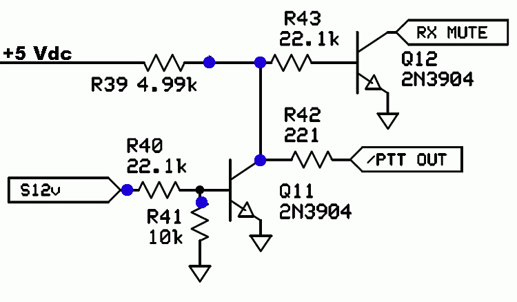
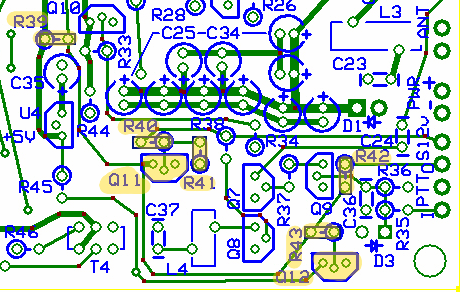
This stage handles the muting of the RX section when I PTT goes high. When RX Mute is High, the RX Mixer is disabled; when RX Mute goes low (the normal power up value), the RX Mixer is enabled.Schematic

Bill of Materials
| Designation | Value | Orientation |
|---|---|---|
| Q11 | 2N3904 NPN | TO 92 |
| Q12 | 2N3904 NPN | TO 92 |
| R39 | 4.99 K, 1/4W, 1% | West-East |
| R40 | 22.1 K, 1/4W, 1% | East-West |
| R41 | 10.0 K, 1/4 W, 1% | South-North |
| R42 | 221, 1/4 W, 1% | North-South |
| R43 | 22.1 K, 1/4W, 1% | East-West |
Build Notes

Testing
Current Draw
- current draw should be at ~38 mA
RX Muting
- set I PTT to high by connecting R33 hairpin to R35 hairpin with a clip lead
- Measure the RX Mute signal (at R45 hairpin). You should get a high signal (~5 Vdc)
- Measure the voltage at the S12V pad. You should get 10-12 Vdc
- set I PTT to low by disconnecting the lead between R33 and R35
- Measure the RX Mute signal (at R45 hairpin). You should get a low signal (~50 mVdc)
- Measure the voltage at the S12V pad. You should get ~0 Vdc