Switches Introduction
General
This stage uses two extremely sensitive components, U1 and U2. Be sure to take appropriate
ESD (anti-static) precautions when working in this stage.
In fact, if you are building this during the "static season", you might want to put off the build/test steps related to these switches until AFTER completing all the other stages.
This stage provides the two FST 3253 1-4 switches to permit switching a particular band's filter "chain" into or out of the board's outputs. The switches essentially "connect" the Input transformer, via a set of filters, to the output transformer
Switches Schematic
(Resistor testpoints (hairpin, top, or left-hand lead), as physically installed on the board, are marked in the schematic with red dots)
(Click for Full Schematic)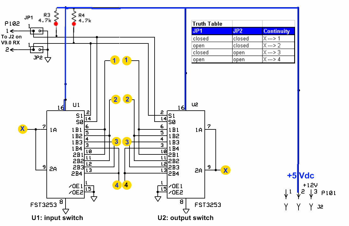 (go directly to build notes)
Switches Bill of Materials
Stage Bill of Materials
(resistor images and color codes courtesy of WIlfried, DL5SWB's R-Color Code program)
| Check | Designation | Component | Marking | Category | Orientation | Notes | Circuit |
|---|---|---|---|---|---|---|---|
| ❏ | U1 | FST3253 mux/demux switch | FST3253
 | SOIC-16 | Switches | ||
| ❏ | U2 | FST3253 mux/demux switch | FST3253
| SOIC-16 | Switches |
Switches Summary Build Notes
- Install FST3253 Switches
- Test the Stage
Switches Detailed Build Notes
Bottom of the Board
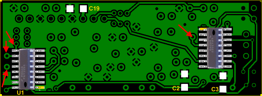
Install FST3253 Switches
Pin 1 is highlighted in the above graphic .
Take care to avoid solder splashovers that can clog up thru-holes for later components. Particularly sensitive sites are indicated in the above graphic by red arrows. If your hands are less than steady, you mat want to insert a toothpick temporarily into the affected thru-hole while soldering in its vicinity.
| Check | Designation | Component | Marking | Category | Orientation | Notes |
|---|---|---|---|---|---|---|
| ❏ | U1 | FST3253 mux/demux switch | FST3253
| SOIC-16 | Take ESD precautions | |
| ❏ | U2 | FST3253 mux/demux switch | FST3253
| SOIC-16 | Take ESD precautions |
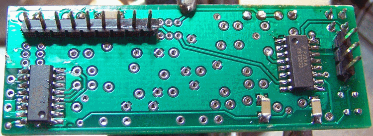
Switches Completed Stage
Bottom of the Board
Switches Testing
ESD
Test Setup
Take ESD precautions when conducting these inspections and tests. The IC switches are extremely sensitive to static damage.
Visual Check
Test Setup
Using very good lighting and magnification, carefully inspect the solder joints to identify bridges, cold joints, or poor contacts.
Pay especial attention to the joints on the two IC's pins. If necessary, touch up the joints with your iron and/or some flux. Wick up any excess.
U1 Continuity Tests (only if necessary)
Test Setup
Normally this test is unnecessary, since the following stage has a simpler, less risky test of the switches' functioning. Conduct this test only in the case that the test in the following stage is not passed. Then, make sure that you have prevented ESD/static discharge via good ESD precautions when conducting this test.
"Continuity" in this case is actually a resistance that is several orders of magnitude below the non-continuity case. Depending upon the ohmmeter, you could see "continuity" indicated by a resistance of between 60 and 90 k ohms; "non-continuity" would be indicated by a resistance of 3 - 6 M ohms.
- The following tests should only be attempted if you have taken good anti-static, ESD precautions, since the potential exists to completely "fry" the FST 3253. This is especially true during the so-called "static season".
- Apply 5 Vdc to the board at P101-2 (+5) and P100-3 (ground)
- For FST 3253 switch U1, measure the continuity between Point X and Points 1, 2, 3, and 4, for each of the appropriate jumper settings on JP1 and JP2
- The terms "open" and "closed" refer to the jumpered status of JP1 and/or JP2. "Open" means not jumpered.

- The nominal result of "X ---> 1" means there is continuity between the 2 points. See testpoints graphic below.
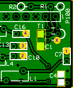
Test Measurements
| Testpoint | Units | Nominal Value | Author's | Yours |
|---|---|---|---|---|
| JP1&2 Closed | k ohm | U1: X --->1 (= 70-100) | ~64 | _______ |
| JP1 Open, JP2 Closed | k ohm | U1: X --->2 (= 70-100) | ~64 | _______ |
| JP1 Closed, JP2 Open | k ohm | U1: X --->3 (= 70-100) | ~64 | _______ |
| JP1&2 Open | k ohm | U1: X --->4 (= 70-100) | ~64 | _______ |
U2 Continuity Tests (only if necessary)
Test Setup
Normally this test is unnecessary, since the following stage has a simpler, less risky test of the switches' functioning. Conduct this test only in the case that the test in the following stage is not passed. Then, make sure that you have prevented ESD/static discharge via good ESD precautions when conducting this test.
"Continuity" in this case is actually a resistance that is several orders of magnitude below the non-continuity case. Depending upon the ohmmeter, you could see "continuity" indicated by a resistance of between 60 and 90 k ohms; "non-continuity" would be indicated by a resistance of 3 - 6 M ohms.
- The following tests should only be attempted if you have taken good anti-static, ESD precautions, since the potential exists to completely "fry" the FST 3253. This is especially true during the so-called "static season".
- Apply 5 Vdc to the board at P101-2 (+5) and P100-3 (ground)
- For FST 3253 switch U2, measure the continuity between Point X and Points 1, 2, 3, and 4, for each of the appropriate jumper settings on JP1 and JP2
- The terms "open" and "closed" refer to the jumpered status of JP1 and/or JP2. "Open" means not jumpered.
- The nominal result of "X ---> 1" means there is continuity between the 2 points. See testpoints graphic below.
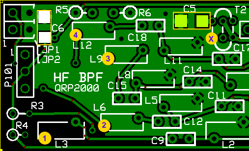
Test Measurements
| Testpoint | Units | Nominal Value | Author's | Yours |
|---|---|---|---|---|
| JP1&2 Closed | k ohm | U2: X --->1 (= 70-100) | ~64 | _______ |
| JP1 Open, JP2 Closed | k ohm | U2: X --->2 (= 70-100) | ~64 | _______ |
| JP1 Closed, JP2 Open | k ohm | U2: X --->3 (= 70-100) | ~64 | _______ |
| JP1&2 Open | k ohm | U2: X --->4 (= 70-100) | ~64 | _______ |