Band1a 6m Introduction
General
The latest design of the HF-BPF kit now permits of two options:
- Option 1: the original design covering 1.8 MHz - 30 mHz, in 4 bands, and
- Option 2: a board covering 3.5 MHz - 30 MHz plus 6m, in 4 bands
These builders notes describe 4 "bands" and the board layout permits filters for four bands. However, depending upon the option (1 or 2), the bands named "band 1" and "band 2" will be built and installed differently. The changes for Band 1 are as follows (and will be implmented somewhat more elegantly in these note, time and resources permitting):
- Band 1 is changed between option 1 (1.8-4 MHz) and option 2 (6m):
- C7: option 1=150 pF; option 2 = 5.6 pF
- C8: option 1=330 pF ; option 2 = 39 pF
- C9: option 1=150 pF ; option 2 = 5.6 pF
- L1: option 1= 23 uH ; option 2 = 1.64 uH
- L2: option 1= 10.7uH; option 2 = not used
- L3: option 1= 23 uH ; option 2 = 1.64 uH
See the detailed techniques for winding toroidial coils
(go directly to build notes)Band1a 6m Schematic
(Resistor testpoints (hairpin, top, or left-hand lead), as physically installed on the board, are marked in the schematic with red dots)
(Click for Full Schematic)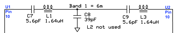 (go directly to build notes)
Band1a 6m Bill of Materials
Stage Bill of Materials
(resistor images and color codes courtesy of WIlfried, DL5SWB's R-Color Code program)
| Check | Designation | Component | Marking | Category | Orientation | Notes | Circuit |
|---|---|---|---|---|---|---|---|
| ❏ | C07 | 5.6 pF 5% | 5.6 | Ceramic | Band1a 6m | ||
| ❏ | L1 | 1.64 uH 23T #30 on T25-6 (15") | yellow
 | Coil | Band1a 6m | ||
| ❏ | C09 | 5.6 pF 5% | 5.6 | Ceramic | Band1a 6m | ||
| ❏ | L3 | 1.64 uH 23T #30 on T25-6 (15") | yellow
| Coil | Band1a 6m | ||
| ❏ | L2 | unused capacitor | Unused | Band1a 6m | |||
| ❏ | C08 | 39pF 5% | 39J | Ceramic | Band1a 6m |
Band1a 6m Summary Build Notes
- Install the Capacitors
- Wind and Install the Coils
- Test the Stage
Band1a 6m Detailed Build Notes
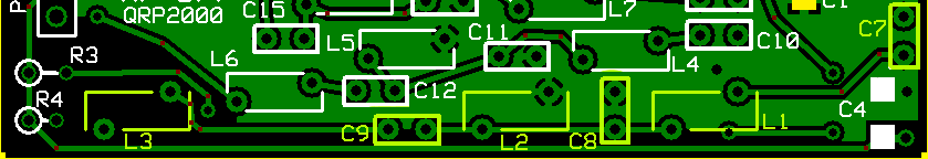
Top of the Board
Install the Capacitors
| Check | Designation | Component | Marking | Category | Orientation | Notes |
|---|---|---|---|---|---|---|
| ❏ | C07 | 5.6 pF 5% | 5.6 | Ceramic | ||
| ❏ | C09 | 5.6 pF 5% | 5.6 | Ceramic | ||
| ❏ | C08 | 39pF 5% | 39J | Ceramic |
Wind and Install the Coils
| Check | Designation | Component | Marking | Category | Orientation | Notes |
|---|---|---|---|---|---|---|
| ❏ | L1 | 1.64 uH 23T #30 on T25-6 (15") | yellow
| Coil | ||
| ❏ | L3 | 1.64 uH 23T #30 on T25-6 (15") | yellow
| Coil | ||
| ❏ | L2 | unused capacitor | Unused |
Band1a 6m Completed Stage
Top of the Board

Band1a 6m Testing
Visual Inspection
Test Setup
Using very good lighting and magnification, carefully inspect the solder joints to identify bridges, cold joints, or poor contacts.
Pay especial attention to the joints on the inductors. If necessary, touch up the joints with your iron and/or some flux.
Continuity Tests
Test Setup
- This tests for continuity in the "chain" of inductors for this band
- The graphic below shows two continuity chains and their associated test points on the bottom of the board.
- The "A and B chains"are shown using lettered dots and lines. :
- For each of the two segments (A-A and B-B), measure the resistance between the dot pairs - you want ~0 ohms.
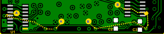
Test Measurements
| Testpoint | Units | Nominal Value | Author's | Yours |
|---|---|---|---|---|
| Point "A" to poin "A"t | ohms | 0 | TBD | _______ |
| Point "A" to poin "A"t | ohms | 0 | TBD | _______ |