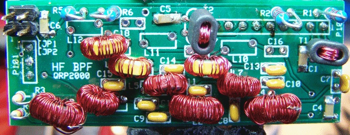
Band 3: 8-16 MHz Introduction
General
See the detailed techniques for winding toroidial coils
Theory of Operation
This stage builds and installs the filter "chain" for Band 3. Refer to Jan G0BBL's Design Plots to see the performance characteristics of this chain.
 Remember, when winding toroidal inductors, a single pass through the core counts as 1 turn. You might want to review
Leonard KC0WOX's excellent 10-minute video on winding toroidal coils.
Band 3: 8-16 MHz Schematic
(Resistor testpoints (hairpin, top, or left-hand lead), as physically installed on the board, are marked in the schematic with red dots)
(Click for Full Schematic) (go directly to build notes)
Band 3: 8-16 MHz Bill of Materials
Stage Bill of Materials
(resistor images and color codes courtesy of WIlfried, DL5SWB's R-Color Code program)
| Check | Designation | Component | Marking | Category | Orientation | Notes | Circuit |
|---|---|---|---|---|---|---|---|
| ❏ | L7-core | T25-6 toroid core | yellow
 | Toroid | Band 3: 8-16 MHz | ||
| ❏ | L8-core | T25-6 toroid core | yellow
 | Toroid | Band 3: 8-16 MHz | ||
| ❏ | L9-core | T25-6 toroid core | yellow
 | Toroid | Band 3: 8-16 MHz | ||
| ❏ | wire 3 | #30 enameled magnetic wire | Misc | Band 3: 8-16 MHz | |||
| ❏ | C13 | 47 pF 5% | 47J | Ceramic | Band 3: 8-16 MHz | ||
| ❏ | L7 | 4 uH 38T #30 on T25-6 (18") | yellow
 | Coil | Band 3: 8-16 MHz | ||
| ❏ | L9 | 4 uH 38T #30 on T25-6 (18") | yellow
 | Coil | Band 3: 8-16 MHz | ||
| ❏ | C14 | 180 pF 5% | 181
 | Ceramic | Band 3: 8-16 MHz | ||
| ❏ | C15 | 47 pF 5% | 47J | Ceramic | Band 3: 8-16 MHz | ||
| ❏ | L8 | 1.1 uH 20T #30 on T25-6 (11") | yellow
 | Coil | Band 3: 8-16 MHz |
Band 3: 8-16 MHz Summary Build Notes
- Install the Capacitors
- Wind and Install the Coils
- Test the Stage
Band 3: 8-16 MHz Detailed Build Notes
Top of the Board

Install the Capacitors
Per Jan, G0BBL, solder the Ceramic Capacitors with a clearance of 1/16" to 1/8" (2mm to 3mm) away from the PCB surface.
| Check | Designation | Component | Marking | Category | Orientation | Notes |
|---|---|---|---|---|---|---|
| ❏ | C13 | 47 pF 5% | 47J | Ceramic | ||
| ❏ | C14 | 180 pF 5% | 181
 | Ceramic | ||
| ❏ | C15 | 47 pF 5% | 47J | Ceramic |
Wind and Install the Coils
| Check | Designation | Component | Marking | Category | Orientation | Notes |
|---|---|---|---|---|---|---|
| ❏ | wire 3 | #30 enameled magnetic wire | Misc | |||
| ❏ | L7 | 4 uH 38T #30 on T25-6 (18") | yellow
 | Coil | ||
| ❏ | L9 | 4 uH 38T #30 on T25-6 (18") | yellow
 | Coil | ||
| ❏ | L8 | 1.1 uH 20T #30 on T25-6 (11") | yellow
 | Coil |
Band 3: 8-16 MHz Completed Stage
Top of the Board

Band 3: 8-16 MHz Testing
Visual Check
Test Setup
Using very good lighting and magnification, carefully inspect the solder joints to identify bridges, cold joints, or poor contacts.
Pay especial attention to the joints on the inductors. If necessary, touch up the joints with your iron and/or some flux.
Continuity Tests
Test Setup
- This tests for continuity in the "chain" of inductors for this band
- The graphic below shows two continuity chains and their associated test points on the bottom of the board.
- The "A and B chains"are shown using lettered dots and lines. :
- For each of the two segments (A-A and B-B), measure the resistance between the dot pairs - you want ~0 ohms.

Test Measurements
| Testpoint | Units | Nominal Value | Author's | Yours |
|---|---|---|---|---|
| Point A to Point A | ohms | 0 | 0 | _______ |
| Point B to Point B | ohms | 0 | 0 | _______ |