Power Supply Introduction
(go directly to build notes)Power Supply Schematic
(Resistor testpoints (hairpin, top, or left-hand lead), as physically installed on the board, are marked in the schematic with red dots)
(Click for Full Schematic)
(go directly to build notes)
Power Supply Bill of Materials
Stage Bill of Materials
(resistor images and color codes courtesy of WIlfried, DL5SWB's R-Color Code program)
| Check | Designation | Component | Marking | Category | Orientation | Notes | Circuit |
|---|---|---|---|---|---|---|---|
| ❏ | C07 | 0.1 uF | (smt) black stripe
 | SMT 1206 | Power Supply | ||
| ❏ | C09 | 0.1 uF | (smt) black stripe
 | SMT 1206 | Power Supply | ||
| ❏ | U1 | LM78L05 voltage regulator | LM78L05
 | TO-92 | Power Supply | ||
| ❏ | D1 | 1N4003 | 1N4003
 | Axial | Power Supply | ||
| ❏ | C06 | 10uF/16 VDC |
 | Electrolytic | Power Supply | ||
| ❏ | C08 | 10uF/16 VDC |
 | Electrolytic | Power Supply | ||
| ❏ | ground lead | shunt wire (cut-off lead) | Cutoff | connect at /ENRX | Power Supply |
Power Supply Summary Build Notes
- Install SMT Caps
- Install Electrolytic Caps
- Install U1
- Install D1
- Install Ground Testpoint
- Test the Stage
Power Supply Detailed Build Notes
Bottom of the Board
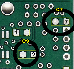
Install SMT Caps
Two SMT capacitors are mounted on the bottom side of the board in the locations shown
| Check | Designation | Component | Marking | Category | Orientation | Notes |
|---|---|---|---|---|---|---|
| ❏ | C07 | 0.1 uF | (smt) black stripe
 | SMT 1206 | ||
| ❏ | C09 | 0.1 uF | (smt) black stripe
 | SMT 1206 |
Top of the Board
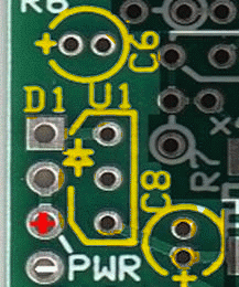
Install Electrolytic Caps
Note that the positive lead on an electrolytic capacitor is the longer lead and goes into the hole marked “+”. The shorter, negative lead is on the side that has a grey band painted from the bottom to the top of the cylinder. Slightly spread the leads of the capacitor on the bottom side of the board to hold it in place and solder one lead. Check that the capacitor has been lightly snugged to the board and reheat the solder if necessary to adjust the position of the capacitor. Solder the second lead and cut both leads flush to the bottom of the board.
| Check | Designation | Component | Marking | Category | Orientation | Notes |
|---|---|---|---|---|---|---|
| ❏ | C06 | 10uF/16 VDC |
 | Electrolytic | ||
| ❏ | C08 | 10uF/16 VDC |
 | Electrolytic |
Install U1
U1 is a 5 volt regulator that will convert the 9-12 vdc input to a well-regulated voltage between 4.6 and 5.4 volts. Mount the U1 on the place provided, paying attention to the silk-screened pattern on the board.The three-hole patterns for mounting U1 are closely spaced and careful soldering is necessary to prevent solder bridges between leads and to make sure each lead is properly soldered.
| Check | Designation | Component | Marking | Category | Orientation | Notes |
|---|---|---|---|---|---|---|
| ❏ | U1 | LM78L05 voltage regulator | LM78L05
 | TO-92 | Take ESD precautions |
Install D1
Mount diode D1 (1N4003) in hairpin fashion, with the anode end flush with the round, lower hole and the band (cathode) end bent into a hairpin inserted into the hole in the square pad. This provides a good measuring point to validate the voltage across C6.
| Check | Designation | Component | Marking | Category | Orientation | Notes |
|---|---|---|---|---|---|---|
| ❏ | D1 | 1N4003 | 1N4003
 | Axial |
Install Ground Testpoint
Using a length of lead that you have cut off after mounting D1, fashion a loop to serve as a ground test point and solder it into the two holes at the lower left hand corner of the board, bridging the two holes.

| Check | Designation | Component | Marking | Category | Orientation | Notes |
|---|---|---|---|---|---|---|
| ❏ | ground lead | shunt wire (cut-off lead) | Cutoff | connect at /ENRX |
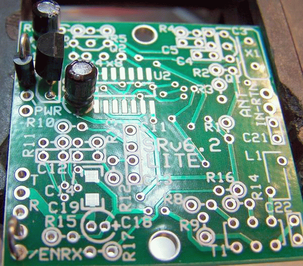
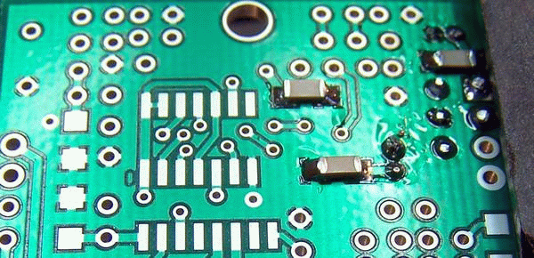
Power Supply Completed Stage
Top of the Board
Bottom of the Board
Power Supply Testing
Visual Inspection
Test Setup
Using very good lighting and magnification, carefully inspect the solder joints to identify bridges, cold joints, or poor contacts.
Current Draw (DMM)
Test Setup
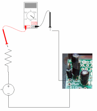
Test for current draw in 2 ways:
- In one test there is also a 1k resistor in the series "chain" as well.
- in the second test, the setup is the same except that the current-liminting resistor is removed
Current draw test below uses a 9 Vdc battery for the power supply
Test Measurements
| Testpoint | Units | Nominal Value | Author's | Yours |
|---|---|---|---|---|
| with limiting resistor | mA | < 9 | 3.97 | _______ |
| no limiting resistor | mA | 3 - 4 | 3.97 | _______ |
Voltages (DMM)
Test Setup
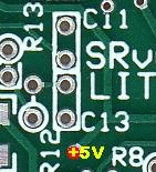
Measure the voltages with respect to ground at the testpoints indicated
Test Measurements
| Testpoint | Units | Nominal Value | Author's | Yours |
|---|---|---|---|---|
| +5V point (see above graphic) | Vdc | 4.5 -5.5 | 4.92 | _______ |