Local Oscillator Introduction
General
Band-Specific Components
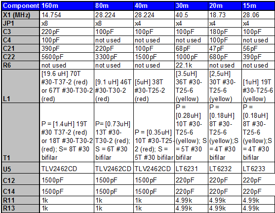
Some of the components in this phase are band-specific. The Bills of Material below specify the common components and the 40m-specific components. If you are building another band's kit, you should refer to the following chart for their component values:
Theory of Operation
The Local Oscillator stage implements a basic Colpitts Crystal Oscillator with a buffer stage to increase the signal level. In the lower band kits, the oscillator produces a signal that is at the crystal's specified fundamental frequency.
The output of this stage is divided by 4 in the follow-on "Divider" stage, producing:- For the 160m, 80m, 40m, 30m kits, the desired center frequency the center frequency for the radio. The incoming RF from the bandpass filter is sampled against this frequency in the QSD Mixer stage.
- For the 20m, 15mkits, a frequency that is one-third of the desired center frequency. The incoming RF from the bandpass filter is sampled against the third harmonic of this frequency in the QSD Mixer stage.
In reality, for each frequency the crystal circuit will oscillate at a slightly lower frequency (~ - 1 kHz), due to the capacitive divider (C10/C11) pulling the crystal down somewhat. The effect is more pronounced for the higher bands.
(go directly to build notes)Local Oscillator Schematic
(Resistor testpoints (hairpin, top, or left-hand lead), as physically installed on the board, are marked in the schematic with red dots)
(Click for Full Schematic)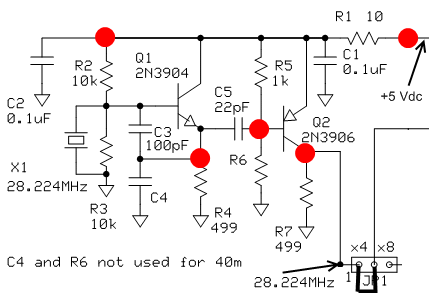
(go directly to build notes)
Local Oscillator Bill of Materials
Stage Bill of Materials
(resistor images and color codes courtesy of WIlfried, DL5SWB's R-Color Code program)
| Check | Designation | Component | Marking | Category | Orientation | Notes | Circuit |
|---|---|---|---|---|---|---|---|
| ❏ | C01 | 0.1 uF | (smt) black stripe
 | SMT 1206 | Local Oscillator | ||
| ❏ | C02 | 0.1 uF | (smt) black stripe
 | SMT 1206 | Local Oscillator | ||
| ❏ | JP1 | shunt wire (cut-off lead) | Cutoff | horizontal | band-specific - see chart. Use a cut-off resistor lead to shunt between holes 1 & 2 of JP1 | Local Oscillator | |
| ❏ | Q1 | 2N3904 NPN Transistor | 2N3904
 | TO-92 | Local Oscillator | ||
| ❏ | Q2 | 2N3906 PNP transistor | 2N3906
 | TO-92 | Local Oscillator | ||
| ❏ | R01 | 10 ohm 1/4W 1% | br-blk-blk-gld-br
 | 1/4W | N-S | Local Oscillator | |
| ❏ | R02 | 10 k 1/4W 1% | br-blk-blk-r-br
 | 1/4W | W-E | Local Oscillator | |
| ❏ | R03 | 10 k 1/4W 1% | br-blk-blk-r-br
 | 1/4W | N-S | Local Oscillator | |
| ❏ | R04 | 499 1/4W 1% | y-w-w-blk-br
 | 1/4W | W-E | Local Oscillator | |
| ❏ | R05 | 1 k 1/4W 1% | br-blk-blk-br-br
 | 1/4W | E-W | Local Oscillator | |
| ❏ | R07 | 499 1/4W 1% | y-w-w-blk-br
 | 1/4W | S-N | Local Oscillator | |
| ❏ | C03 | 100 pF 5% | 101
 | Ceramic | band-specific - see chart | Local Oscillator | |
| ❏ | C05 | 22 pF 5% | 22J
 | Ceramic | Local Oscillator | ||
| ❏ | C04 | 100 pF 5% | 101
 | Ceramic | band-specific - see chart. Used only in 160, 30, and 20m kits | Local Oscillator | |
| ❏ | X1 | 28.224 MHz Crystal | 28.224 or 28.2C69 | Xtal | band-specific - see chart | Local Oscillator | |
| ❏ | R06 | 22.1k 1/4W 1% | r-r-brn-r-br
 | 1/4W | only used in 30m Kit | Local Oscillator |
Local Oscillator Summary Build Notes
- Install SMT Caps
- Install JP1 Bridge loop
- Install Transistors
- Install Resistors
- Install Ceramic Capacitors
- Install Crystal
- Test the Stage
Local Oscillator Detailed Build Notes
Bottom of the Board
Install SMT Caps
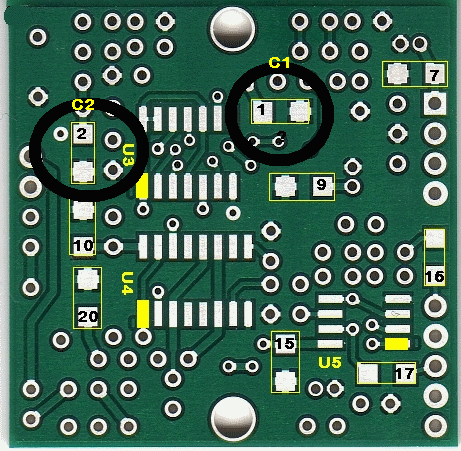
Install the two SMT Caps (C1 and C2) on the bottom side of the board
| Check | Designation | Component | Marking | Category | Orientation | Notes |
|---|---|---|---|---|---|---|
| ❏ | C01 | 0.1 uF | (smt) black stripe
 | SMT 1206 | ||
| ❏ | C02 | 0.1 uF | (smt) black stripe
 | SMT 1206 |
Top of the Board
Install JP1 Bridge loop
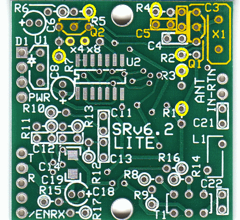
Mount a small wire loop to bridge the x4 holes, holes 1 and 2, of JP1. (This will result in each crystal frequency being divided by four in the clocking of the QSD and QSE circuits. The center frequency resulting from the x4 jumper will be approximately the crystal frequency divided by four, or 7.056 MHz)
| Check | Designation | Component | Marking | Category | Orientation | Notes |
|---|---|---|---|---|---|---|
| ❏ | JP1 | shunt wire (cut-off lead) | Cutoff | horizontal | band-specific - see chart. Use a cut-off resistor lead to shunt between holes 1 & 2 of JP1 |
Install Transistors
Install the transistors, Q1 and Q2. Use the body shape silk screen marking to help in proper placement of each transistor.
Caution: be sure to carefully observe the markings on the transistors and distinguish the 3904 (Q1) from the 3906 (Q2) Getting these mixed up could damage the transistors and cause excessive load on the voltage regulator!
- Q1 2N3904 (next to X1)
- Q2 2N3906 (left of top mounting hole)
| Check | Designation | Component | Marking | Category | Orientation | Notes |
|---|---|---|---|---|---|---|
| ❏ | Q1 | 2N3904 NPN Transistor | 2N3904
 | TO-92 | ||
| ❏ | Q2 | 2N3906 PNP transistor | 2N3906
 | TO-92 |
Install Resistors
Install resistors R1 through R5 and R7. Resistors are typically mounted on the board in a hairpin fashion with the body of each resistor located over its silkscreen circle. This is important because the test points (red dots on the schematics) are at the tops of the hairpins, are based on the assumption that this installation technique was used.
Normally, you will only need R6 for the 30m rig. R6 in the SoftRock Lite kit is only needed if the clock signal from Q2 to U2 does not result in proper clocking of U2. A value of R6 between 12k and 22.1k may be used if needed.
| Check | Designation | Component | Marking | Category | Orientation | Notes |
|---|---|---|---|---|---|---|
| ❏ | R01 | 10 ohm 1/4W 1% | br-blk-blk-gld-br
 | 1/4W | N-S | |
| ❏ | R02 | 10 k 1/4W 1% | br-blk-blk-r-br
 | 1/4W | W-E | |
| ❏ | R03 | 10 k 1/4W 1% | br-blk-blk-r-br
 | 1/4W | N-S | |
| ❏ | R04 | 499 1/4W 1% | y-w-w-blk-br
 | 1/4W | W-E | |
| ❏ | R05 | 1 k 1/4W 1% | br-blk-blk-br-br
 | 1/4W | E-W | |
| ❏ | R07 | 499 1/4W 1% | y-w-w-blk-br
 | 1/4W | S-N | |
| ❏ | R06 | 22.1k 1/4W 1% | r-r-brn-r-br
 | 1/4W | only used in 30m Kit |
Install Ceramic Capacitors
Note: C4 is only used in the 160, 30, and 20m kits
| Check | Designation | Component | Marking | Category | Orientation | Notes |
|---|---|---|---|---|---|---|
| ❏ | C03 | 100 pF 5% | 101
 | Ceramic | band-specific - see chart | |
| ❏ | C05 | 22 pF 5% | 22J
 | Ceramic | ||
| ❏ | C04 | 100 pF 5% | 101
 | Ceramic | band-specific - see chart. Used only in 160, 30, and 20m kits |
Install Crystal
Mount the HC49 crystal mounting in the upper right corner of the board, mounting it vertically to the board. A small plated-through hole in the lower left corner of the crystal mounting position (blue hole in illustration at right) provides a place for a grounding wire to be soldered to the metal crystal case. The grounding wire also provides additional mechanical support for the crystal. Make sure the crystal is mounted slightly above the board since a trace runs on top of the board from one of the crystal holes to the base of Q1. You can use a piece of cardboard or wire insulation between the bottom of the crystal and the board to get the desired standoff distance while mounting X1.
| Check | Designation | Component | Marking | Category | Orientation | Notes |
|---|---|---|---|---|---|---|
| ❏ | X1 | 28.224 MHz Crystal | 28.224 or 28.2C69 | Xtal | band-specific - see chart |
Local Oscillator Completed Stage
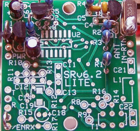
Top of the Board
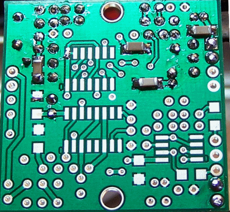
Bottom of the Board
Local Oscillator Testing
Visual Inspection
Test Setup
Using very good lighting and magnification, carefully inspect the solder joints to identify bridges, cold joints, or poor contacts.
Current draw (using 9V battery)
Test Setup
- connect a 1k ohm resistor in series with the positive power lead
- apply 9 Vdc and measure the current draw with the limiting resistor in place
- remove the current limiting resistor
- apply 9 Vdc and measure the current draw without the limiting resistor
Test Measurements
| Testpoint | Units | Nominal Value | Author's | Yours |
|---|---|---|---|---|
| Current draw with 9 Vdc and NO limiting resistor | mA | 10 - 12 | 10.9 | _______ |
| Current draw with 9 Vdc and 10k limiting resistor | mA | < 9 | 6 | _______ |
Voltage Tests
Test Setup
- Power up the board
- measure the voltages with respect to ground

Test Measurements
| Testpoint | Units | Nominal Value | Author's | Yours |
|---|---|---|---|---|
| R1 hairpin lead | Vdc | 4.5 - 5.4 | 4.92 | _______ |
| Collector of Q1/Emitter of Q2 (R2 hairpin) | Vdc | 4.4 - 5.3 | 4.87 | _______ |
| Base of Q1 (see bottomside view, above) | Vdc | 2.1 - 2.6 | 2.34 | _______ |
| Emitter of Q1 (R4 hairpin - s/b 0.7 V lesss than Q1 base | Vdc | 1.4 - 1.9 | 1.65 | _______ |
| Base of Q2 (R5 hairpin) | Vdc | 4.4 - 5.3 | 4.87 | _______ |
| Jumper lead of JP1 | Vdc | 2.9 - 3.5 | 3.21 | _______ |
LO Output
Test Setup
- The frequency of the LO’s output should be 4 times the desired center frequency 7.056 MHz, or 28.224 MHz.
- Check this if you have a good frequency counter and/or scope, or a receiver you can tune into 28.224 MHz.
- Scope measurements may be taken IF you have a high quality, calibrated scope with correctly compensated probes
- Note: if your kit is the 20m kit, this is a little different. The Upgraded 20m SoftRock Lite kit uses 1/3 sub-harmonic sampling to give 20m receive function. The center frequency is approximately 3 * 18.73 / 4 = 14.047 MHz. The loss in sensitivity associated with the 1/3 sub-harmonic sampling, about 3 or 4 dB, is made up by 5x gain, (compared to the 40m SoftRock Lite), in the I / Q audio stage where a low-noise LT6231 op-amp is used in lieu of the TVL2462CD opamps
Test Measurements
| Testpoint | Units | Nominal Value | Author's | Yours |
|---|---|---|---|---|
| Radio tuned to 28.224 MHz, short wire antenna | receives | Yes or No (want YES) | Yes | _______ |
| Scope - probe on Jp1 jumper lead | MHz (approx) | 28.224 | 27.78 | _______ |
| p_p voltage (scope) - square wave | Vp-p | 3.3 | n/a | _______ |