BPF Introduction
General
This stage builds the bandpass filter that is the RF front-end for the radio. RF arriving via the floating antenna terminals (Note: no ground connection) is filtered and coupled to the mixer stage.
Band-Specific Components
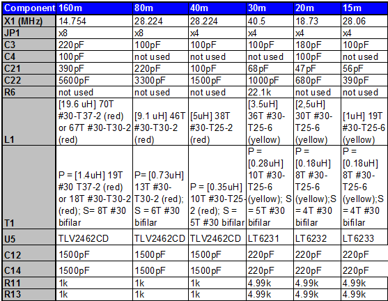
Some of the components in this phase are band-specific. The Bills of Material below specify the common components and the 40m-specific components. If you are building another band's kit, you should refer to the following chart for their component values:
 (go directly to build notes)
BPF Schematic
(Resistor testpoints (hairpin, top, or left-hand lead), as physically installed on the board, are marked in the schematic with red dots)
(Click for Full Schematic)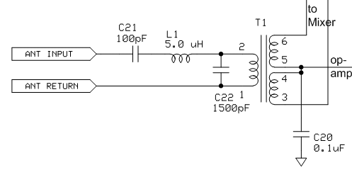
(go directly to build notes)
BPF Bill of Materials
Stage Bill of Materials
(resistor images and color codes courtesy of WIlfried, DL5SWB's R-Color Code program)
| Check | Designation | Component | Marking | Category | Orientation | Notes | Circuit |
|---|---|---|---|---|---|---|---|
| ❏ | C20 | 0.1 uF | (smt) black stripe
 | SMT 1206 | BPF | ||
| ❏ | C21 | 100 pF 5% | 101
 | Ceramic | band-specific - see chart | BPF | |
| ❏ | C22 | 1500 pF 10% | 152
 | Ceramic | band-specific - see chart | BPF | |
| ❏ | core1 | T25-2 toroid core | red
 | Toroid | band-specific - see chart | BPF | |
| ❏ | L1 | 5.0 uH 38T #30 T25-2 (17") | red | Coil | band-specific - see chart | BPF | |
| ❏ | core2 | T25-2 toroid core | red
 | Toroid | band-specific - see chart | BPF | |
| ❏ | T1 | 0.35 uH 10T/2x5T bifilar #30 on T25-2 (7") | red
 | Xfrmr | band-specific - see chart | BPF |
BPF Summary Build Notes
- Install SMT Cap
- Wind and Install L1
- Wind and Install T1
- Install Ceramic Caps
- Test the Stage
BPF Detailed Build Notes
Bottom of the Board
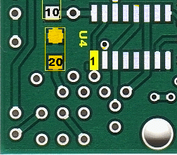
Install SMT Cap
| Check | Designation | Component | Marking | Category | Orientation | Notes |
|---|---|---|---|---|---|---|
| ❏ | C20 | 0.1 uF | (smt) black stripe
 | SMT 1206 |
Top of the Board
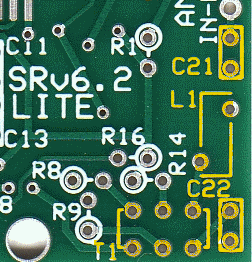
Wind and Install L1
L1: wind 38 turns of #30 wire (requires about 14” of wire) onto a T25-2 (Red) toroid core. This should produce a 5 uH inductance. Each pass through the center of the core is counted as a turn when winding the inductor. L1 is mounted vertically and supported by its leads. Be sure to remove the enamel coating on the wire before attempting to solder an inductor lead to its associated mounting hole. The enamel coating on the #30 wire provided in the kit does not heat strip very well but may be stripped by use of a small folded over piece of Emory paper where the lead is pulled through two facing surfaces of the Emory paper multiple times to sand off the enamel coating on the wire end
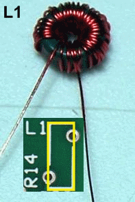
| Check | Designation | Component | Marking | Category | Orientation | Notes |
|---|---|---|---|---|---|---|
| ❏ | L1 | 5.0 uH 38T #30 T25-2 (17") | red | Coil | band-specific - see chart |
Wind and Install T1
If T1 is not wired correctly to the six holes on the Lite circuit board it can result in very low receiver sensitivity.
- This transformer has a single winding primary and a bifilar winding secondary, wound with #30 wire onto a T25-2 (red) toroid. The 10 turn primary winding, using 10” of #30 wire, should yield 0.35 uH. The 5 turn secondary uses two 5” lengths of #30 wire, twisted together into a bifilar pair that has approximately 2-3 twists per inch.
- Transformer T1 is mounted vertically and raised above the board about 1/8 of an inch. In winding T1, first wind the primary winding with 10 turns #30 AWG enameled wire (approximately 10” of wire) so that the primary winding starts and ends at about the same point on the core and is uniformly spread around the core. Twist two 5” pieces of #30 enameled wire together and wind the secondary windings with the windings starting and ending just slightly clockwise around the core from where the primary winding starts and ends.
- After striping and tinning each transformer lead at about 1/8 of an inch from the core, determine the two pairs of leads of each of the secondary windings by use of an ohmmeter. I like to use short lengths of insulation from hookup wire to identify two of the 3 sets of leads in these transformers.
- Correct wiring is with lead from one side of the core going to a group of three holes and the leads from the order side of the core goin to the other group of three holes as shown below.
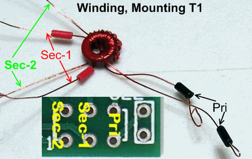
| Check | Designation | Component | Marking | Category | Orientation | Notes |
|---|---|---|---|---|---|---|
| ❏ | T1 | 0.35 uH 10T/2x5T bifilar #30 on T25-2 (7") | red
 | Xfrmr | band-specific - see chart |
Install Ceramic Caps
| Check | Designation | Component | Marking | Category | Orientation | Notes |
|---|---|---|---|---|---|---|
| ❏ | C21 | 100 pF 5% | 101
 | Ceramic | band-specific - see chart | |
| ❏ | C22 | 1500 pF 10% | 152
 | Ceramic | band-specific - see chart |
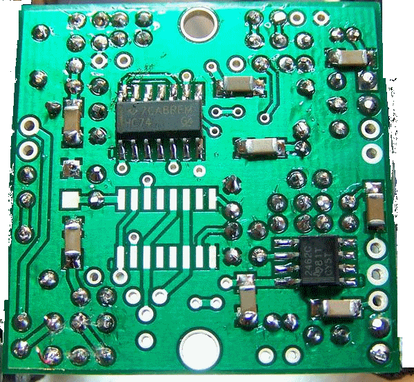
BPF Completed Stage
Top of the Board
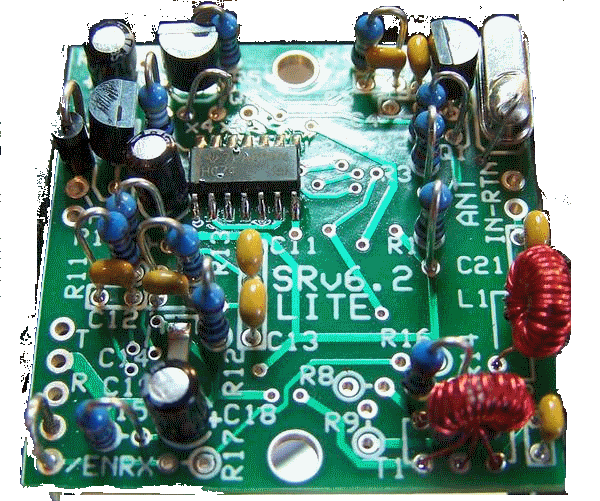
Bottom of the Board
BPF Testing
Visual Inspection
Test Setup
Using very good lighting and magnification, carefully inspect the solder joints to identify bridges, cold joints, or poor contacts.
Pay especial attention to the joints on the transformer. Bad solder joints in this stage will have an extreme effect on the sensitivity of the receiver.
Inductor Continuity Tests (no power)
Test Setup
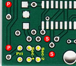
This tests the continuity through L1 and the T1 primary winding, using testpoints (red dot with letter "P") that test the continuity from connected pads. This helps check the soldering of the leads by placing the probes at points that are connected to the actual solder joint.
Similarly, the secondary windings of T1 are tested for continuity, using the secondary testpoints (red dots woth the letter "S").
Test Measurements
| Testpoint | Units | Nominal Value | Author's | Yours |
|---|---|---|---|---|
| L1 and T1 primary (red dots with letter "P") | ohms | 0 | 0 | _______ |
| T1, Secondaries (red dots with letter "S") | ohms | 0 | 0 | _______ |
Voltages
Test Setup
Power-on the board and measure the voltages with respect to ground (WRT) at the designated voltage test points (red dots with letter "S")
Voltages are nominally ½ the 5 volt rail value. However, component tolerances permit a +/- 10% range.

Test Measurements
| Testpoint | Units | Nominal Value | Author's | Yours |
|---|---|---|---|---|
| First red dot with letter "S" wrt ground | Vdc | 2,5 | 2.48 | _______ |
| Second red dot with letter "S" wrt ground | Vdc | 2,5 | 2.48 | _______ |
Transformer Test
Test Setup
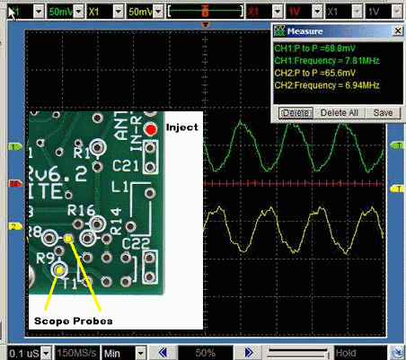
Optional Test - assuming you have a dual channel scope and an RF source that can output 7MHz signal
- Conduct this test with the power OFF
- Inject a ~2 volt p-p signal at around 7 MHz into the ANT-IN pad. You can probably just use a cutoff component lead and poke it through the empty lead hole without soldering
- Set up the scope for triggering on Channel 1 .
- Connect the scope probes to the points shown (yellow dots) below and connect the probe ground leads to ground.
- You should have an equal amplitude, opposite phase signal displayed. If they are in phase, you probably aren't triggering the scope on channel 1. If either one is missing, double check the solder connections for T1.
- Thanks to Leonard KC0WOX for this test
